Digital Electronics Basics
Number Systems & Number Conversion
1's Complement , 2's Complement
9's Complement , 10's Complement
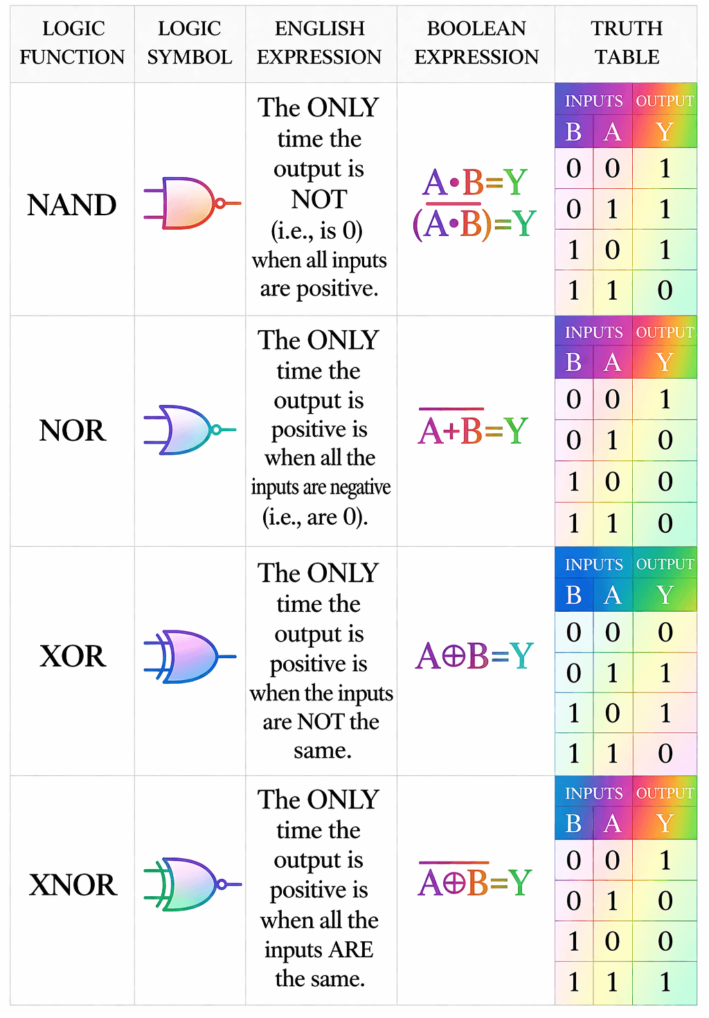
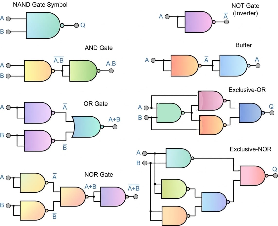
Different Types Logic gate: Basic Logic Gate, Universal Logic Gate
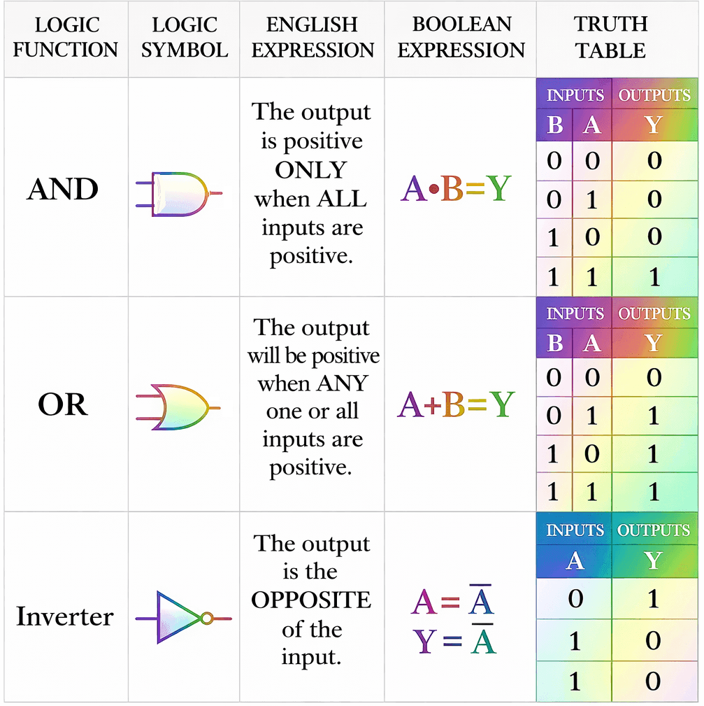
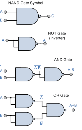
1. NOT gate:
\( Y = \overline{A \cdot A} \)
Explanation:
NAND definition → \( \overline{A \cdot B} \)
Put both inputs same (A = B) → \( \overline{A \cdot A} = \overline{A} \)
2. AND gate:
Explanation:
A AND B = \( A \cdot B \)
NAND gives complement → \( \overline{A \cdot B} \)
So invert again using NAND:
\( A \cdot B = \overline{\overline{A \cdot B}} \)
3. OR gate:
\( Y = \overline{\overline{A \cdot A} \cdot \overline{B \cdot B}} \)
Explanation:
From De Morgan:
\( A + B = \overline{\overline{A} \cdot \overline{B}} \)
4. XOR gate: (Using 4 NAND Gates)
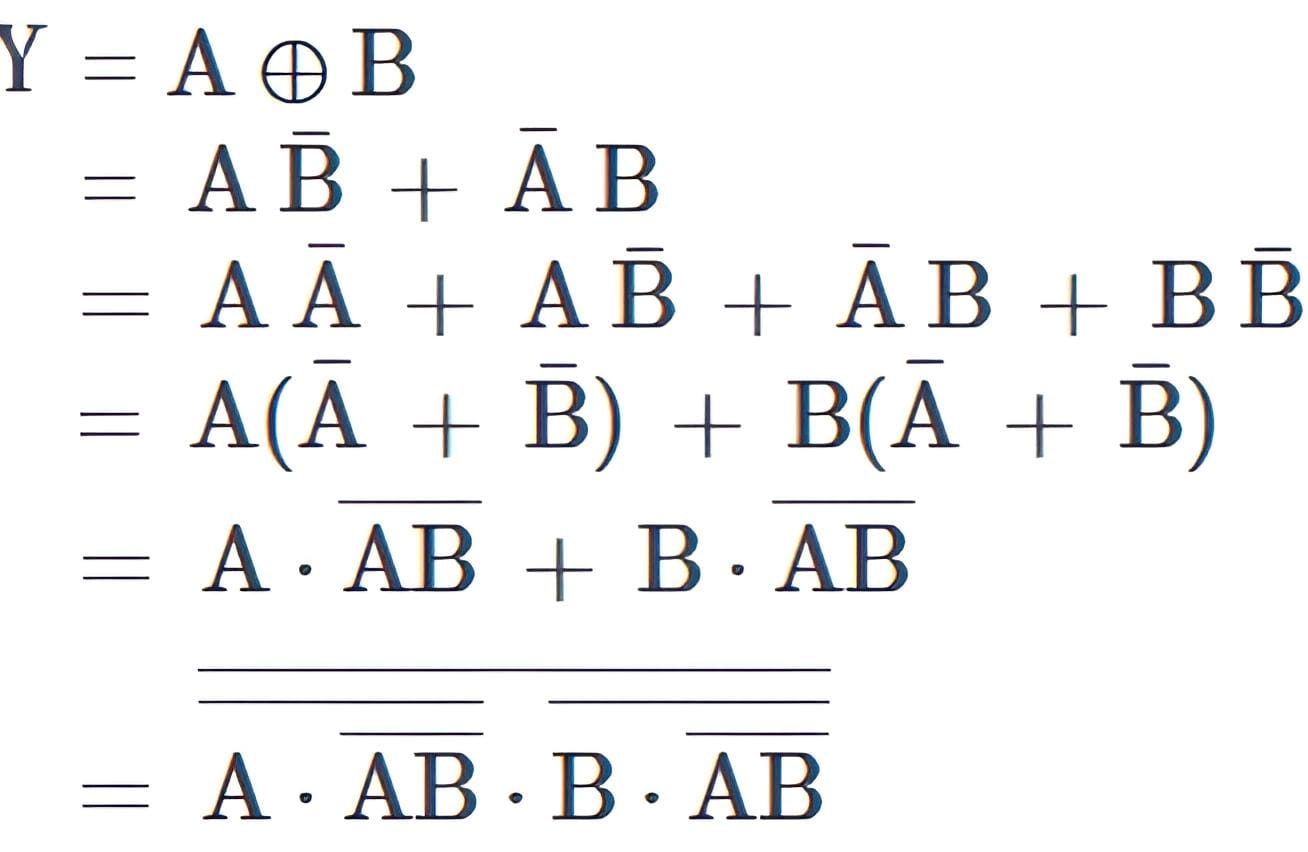
5. XNOR gate:
A ⊙ B = AB + A’B’
= [(AB + A’B’)’]’
= (AB)’.(A’B’)’ [deMorgan’s Law]
6. Buffer gate:
\( Y = \overline{\overline{A \cdot A} \cdot \overline{A \cdot A}} \)
Explanation:
First NAND → \( \overline{A} \)
Second NAND → \( A \)
7. NOR gate:
(A+B)’ = [[(A+B)’]’]’
= [(A’.B’)’ ]’ [deMorgan’s Law]
1. NOT gate:
\( Y = \overline{A + A} \)
Explanation:
NOR definition → \( \overline{A + B} \)
Put both inputs same (A = B) → \( \overline{A + A} = \overline{A} \)
2. OR gate:
\( A + B = \overline{\overline{A + B}} \)
3. AND gate:
Y = A . B = [(A . B)’]’ = [A’+B’]’
4. XNOR gate: (Using NOR gates)
\( Y = \overline{ \left(\overline{A + \overline{A + B}}\right) + \left(\overline{B + \overline{A + B}}\right) } \)
5. XOR gate:
A xor B = A’B + AB’ = AA’+A’B+BB’+AB’
=A'(A+B)+B'(A+B)
=(A+B).(A’+B’)
=[(A+B)’+(A’+B’)’]’
6. Buffer gate:
\( Y = \overline{\overline{A + A} + \overline{A + A}} \)
Explanation:
First NOR → \( \overline{A} \)
Second NOR → \( A \)
7. NAND gate:
(A.B)’ = ((A’+B’)’)’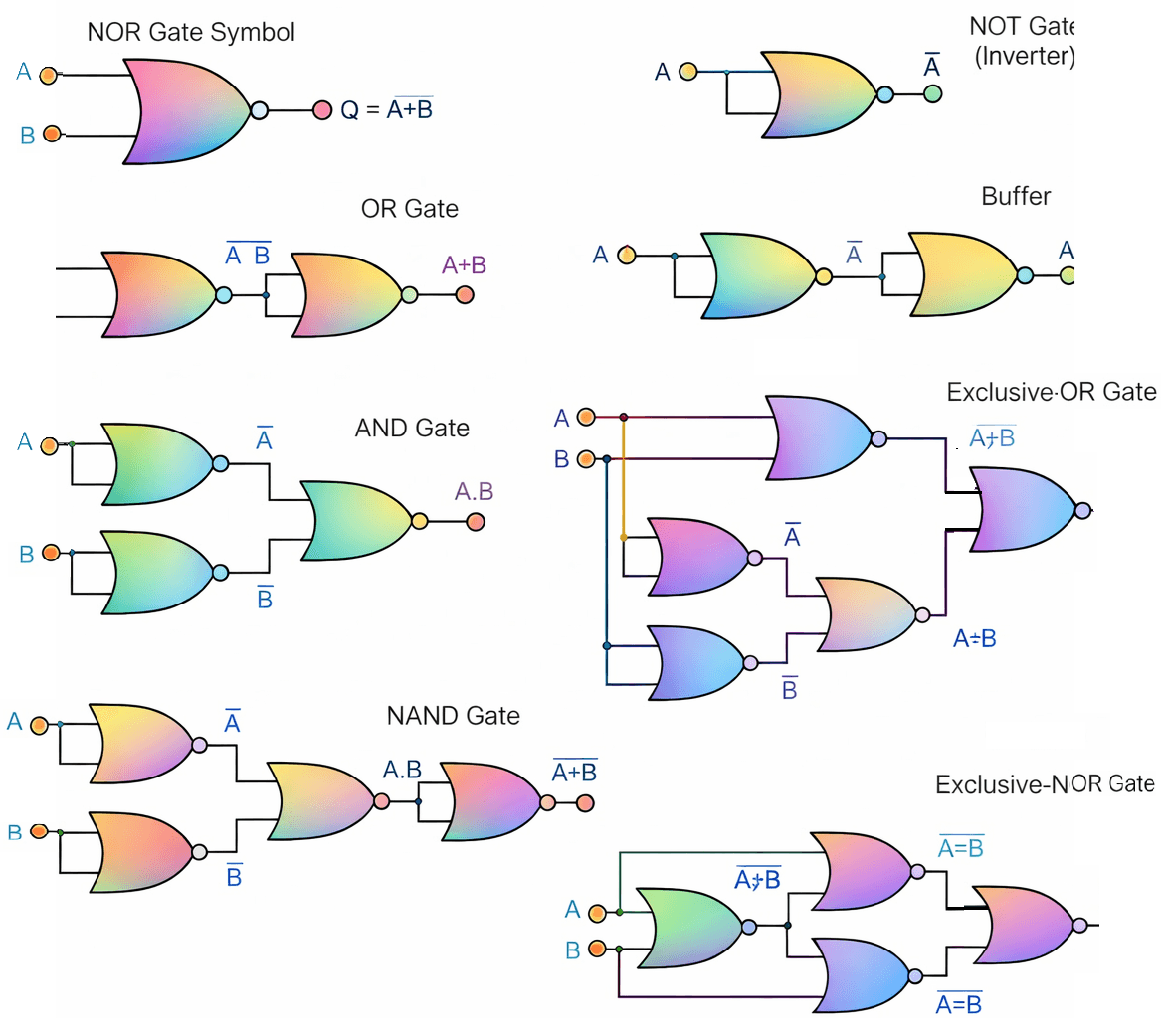
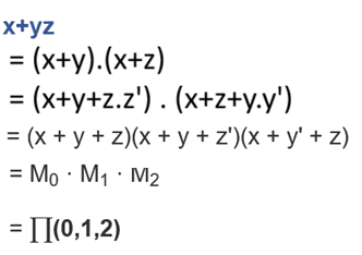
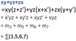
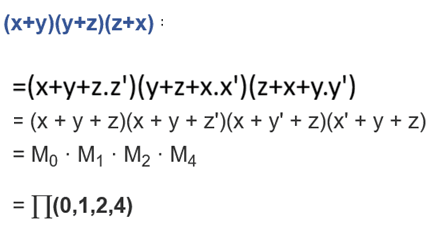
Boolean Algebra, Boolean Function, POS, SOP, Maxterm, Minterm
S. No. | X | Y | Z | Minterms (Product Terms) | Maxterms (Sum Terms) |
|---|---|---|---|---|---|
| 0 | 0 | 0 | 0 | m0 = X’.Y’.Z’ | M0 = X + Y + Z |
| 1 | 0 | 0 | 1 | m1 = X’.Y’.Z | M1 = X + Y + Z’ |
| 2 | 0 | 1 | 0 | m2 = X’.Y.Z’ | M2 = X + Y’ + Z |
| 3 | 0 | 1 | 1 | m3 = X’.Y.Z | M3 = X + Y’ + Z’ |
| 4 | 1 | 0 | 0 | m4 = X.Y’.Z’ | M4 = X’ + Y + Z |
| 5 | 1 | 0 | 1 | m5 = X.Y’.Z | M5 = X’ + Y + Z’ |
| 6 | 1 | 1 | 0 | m6 = X.Y.Z’ | M6 = X’ + Y’ + Z |
| 7 | 1 | 1 | 1 | m7 = X.Y.Z | M7 = X’ + Y’ + Z’ |
SOP conversion
Y = (A+BC) (B+AC’)
= AB+AAC’+BBC+ABCC’
=AB+AC’+BC [SOP]
POS conversion
Y = (A+BC) (B+AC’)
=(A+B).(A+C)(B+A)(B+C’)
=(A+B)(A+C)(B+C’)
Boolean Function Simplification, K-map
A’BC+ABC’+ABC
=BC(A’+A)+ABC’
=BC+ABC’
= B(C+AC’)
= B[(C+A)(C+C’)]
=B(A+C)
A(B’+C)+AB+B'(C+A’)
=AB’+AC+AB+B’C+B’A’
=AB’+AB+AC+B’C+A’B’
=A(B’+B)+AC+B’C+A’B’
=A+AC+B’C+A’B’
=A+B’C+A’B’
=A+(A’+C)B’
=A+A’B’+CB’
=(A+A’)(A+B’)+CB’
=(A+B’)+CB’
=B’+A+CB’
=A+B’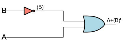
Combinational Circuits: Half Adder, Full Adder, Subtractor, Parrallel Adder
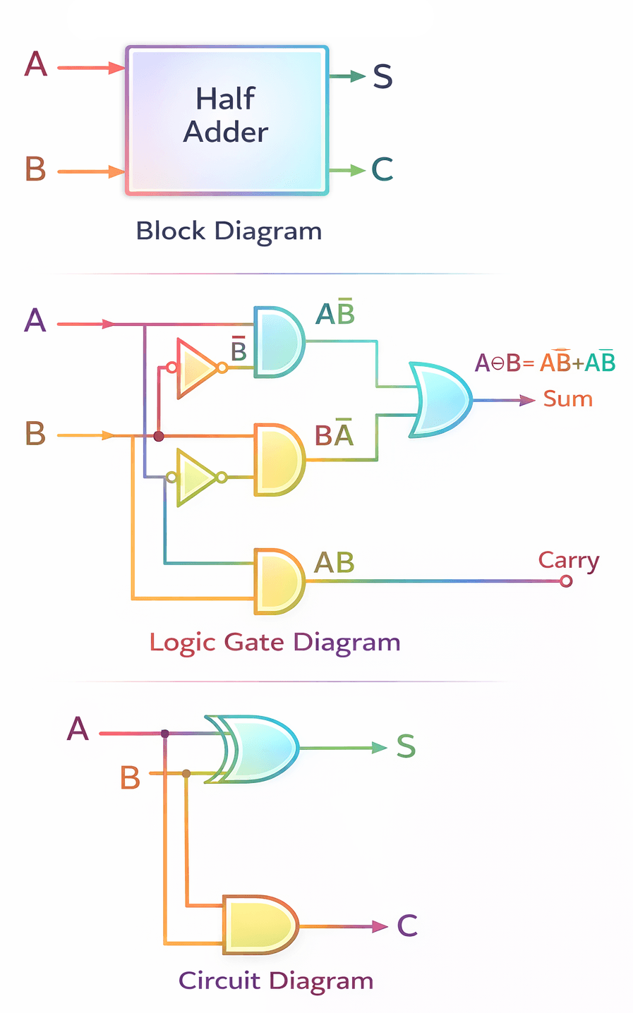
A combinational logic circuit which is designed to add two binary digits is called as a half adder. The half adder provides the output along with a carry value (if any).
| Inputs | Outputs | ||
|---|---|---|---|
| A | B | S (Sum) | C (Carry) |
| 0 | 0 | 0 | 0 |
| 0 | 1 | 1 | 0 |
| 1 | 0 | 1 | 0 |
| 1 | 1 | 0 | 1 |
The sum (S) of the half-adder is the XOR of A and B. Thus,
Sum,S=AB′+A′B=A⊕B
The carry (C) of the half-adder is the AND of A and B. Therefore,
Carry,C=A⋅B
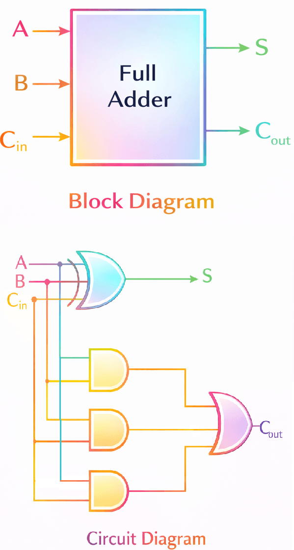
A combinational logic circuit that can add two binary digits (bits) and a carry bit, and produces a sum bit and a carry bit as output is known as a full-adder
| Inputs | Outputs | |||
|---|---|---|---|---|
| A | B | Cin | S (Sum) | Cout (Carry) |
| 0 | 0 | 0 | 0 | 0 |
| 0 | 0 | 1 | 1 | 0 |
| 0 | 1 | 0 | 1 | 0 |
| 0 | 1 | 1 | 0 | 1 |
| 1 | 0 | 0 | 1 | 0 |
| 1 | 0 | 1 | 0 | 1 |
| 1 | 1 | 0 | 0 | 1 |
| 1 | 1 | 1 | 1 | 1 |
Without K-map
S= A′B′Cin+A′BC′in+AB′C′in+ ABCin
= Cin(A′B′ + AB) + C′in(A′B + AB′)
= Cin(A ⊙ B) + C′in(A ⊕ B)
= (A ⊕ B)′Cin + (A ⊕ B)C′in
=(A ⊕ B) ⊕ Cin [ x⊕y=xy’+x’y]
COUT = A′BCin + AB′Cin + ABC′in + ABCin
= Cin(A′B + AB′ + AB) + ABC′in
=Cin (A’B+A(B+B’))+ABC′in
=Cin (A’B+A)+ABC′in
=Cin (A’+A)(B+A)+ABC′in
= Cin(A + B) + ABC′in
= ACin + BCin + ABC′in
= A(Cin + BC′in) + BCin
= A[(Cin + B)(Cin + C′in)] + BCin
= A(B + Cin) + BCin
= AB + ACin + BCin
=AB + ACin + BCin
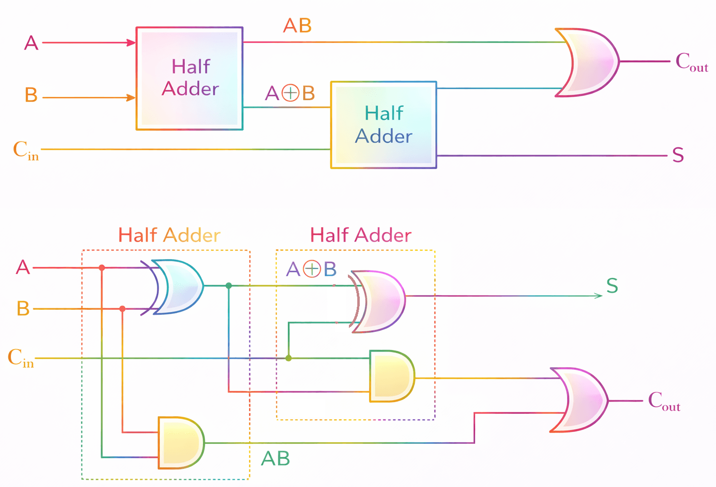
Half Adder Equations:
S₁ = A ⊕ B
C₁ = AB
Second Half Adder (with Cin)
S = S₁ ⊕ Cin = (A ⊕ B) ⊕ Cin
C₂ = S₁ · Cin = (A ⊕ B)Cin
Final Carry:
Cout = C₁ + C₂ = AB + (A ⊕ B)Cin
=AB + ACin + BCin
Explanation
Cout = AB + (A ⊕ B)Cin
= AB + (A′B + AB′)Cin
= AB + A′BCin + AB′Cin
= AB + ACin(A′ + B′) + BCin(A′ + A)
= AB + ACinA′ + ACinB′ + BCin
= AB + ACin + BCin
=AB + ACin + BCin
| Inputs | Outputs | ||
|---|---|---|---|
| A | B | D (Difference) | B (Borrow) |
| 0 | 0 | 0 | 0 |
| 0 | 1 | 1 | 1 |
| 1 | 0 | 1 | 0 |
| 1 | 1 | 0 | 0 |
Difference, d = A′B+AB′ = A⊕B
Borrow, b = A′B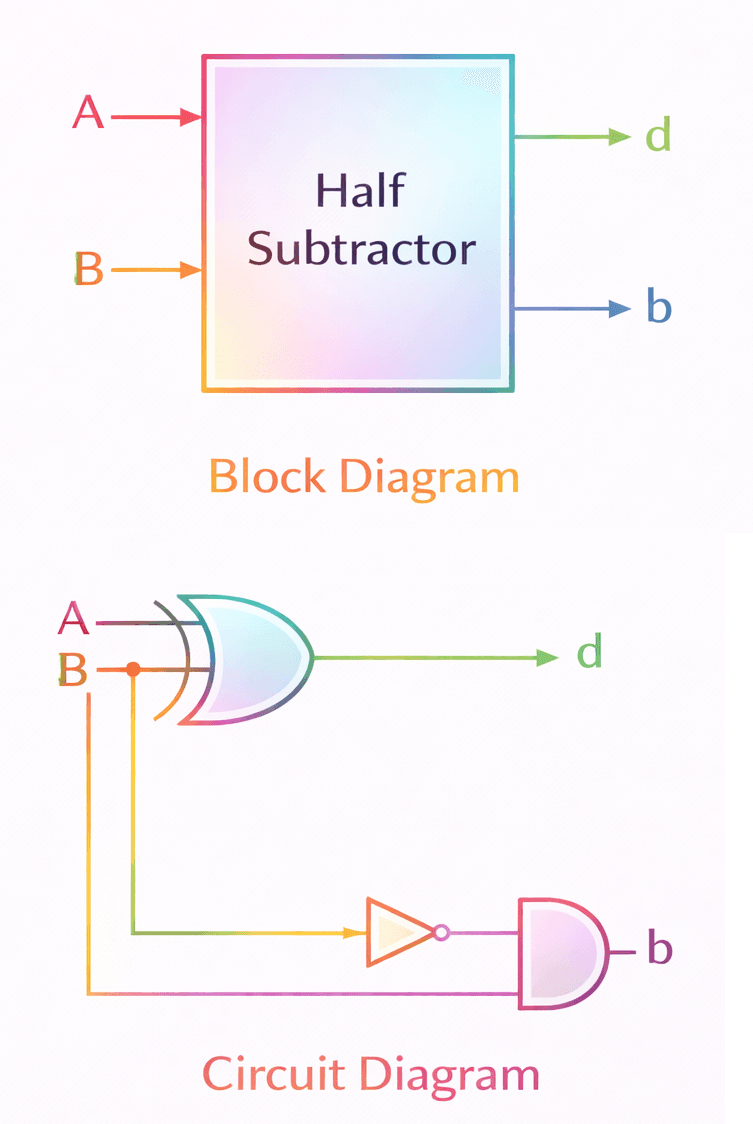
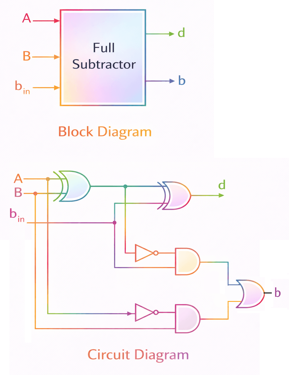
| Inputs | Outputs | |||
|---|---|---|---|---|
| A | B | bin | D (Difference) | B (Borrow) |
| 0 | 0 | 0 | 0 | 0 |
| 0 | 0 | 1 | 1 | 1 |
| 0 | 1 | 0 | 1 | 1 |
| 0 | 1 | 1 | 0 | 1 |
| 1 | 0 | 0 | 1 | 0 |
| 1 | 0 | 1 | 0 | 0 |
| 1 | 1 | 0 | 0 | 0 |
| 1 | 1 | 1 | 1 | 1 |
From Truth Table
Difference, d = A′B′bin+AB′b′in+A′Bb′in+ABbin =A⊕B⊕bin
Borrow,b=A′B′bin+A′Bb′in+A′Bbin+ABbin
Borrow,b=A′B(bin+b′in)+(AB+A′B′)bin=A′B+(A⊕B)′bin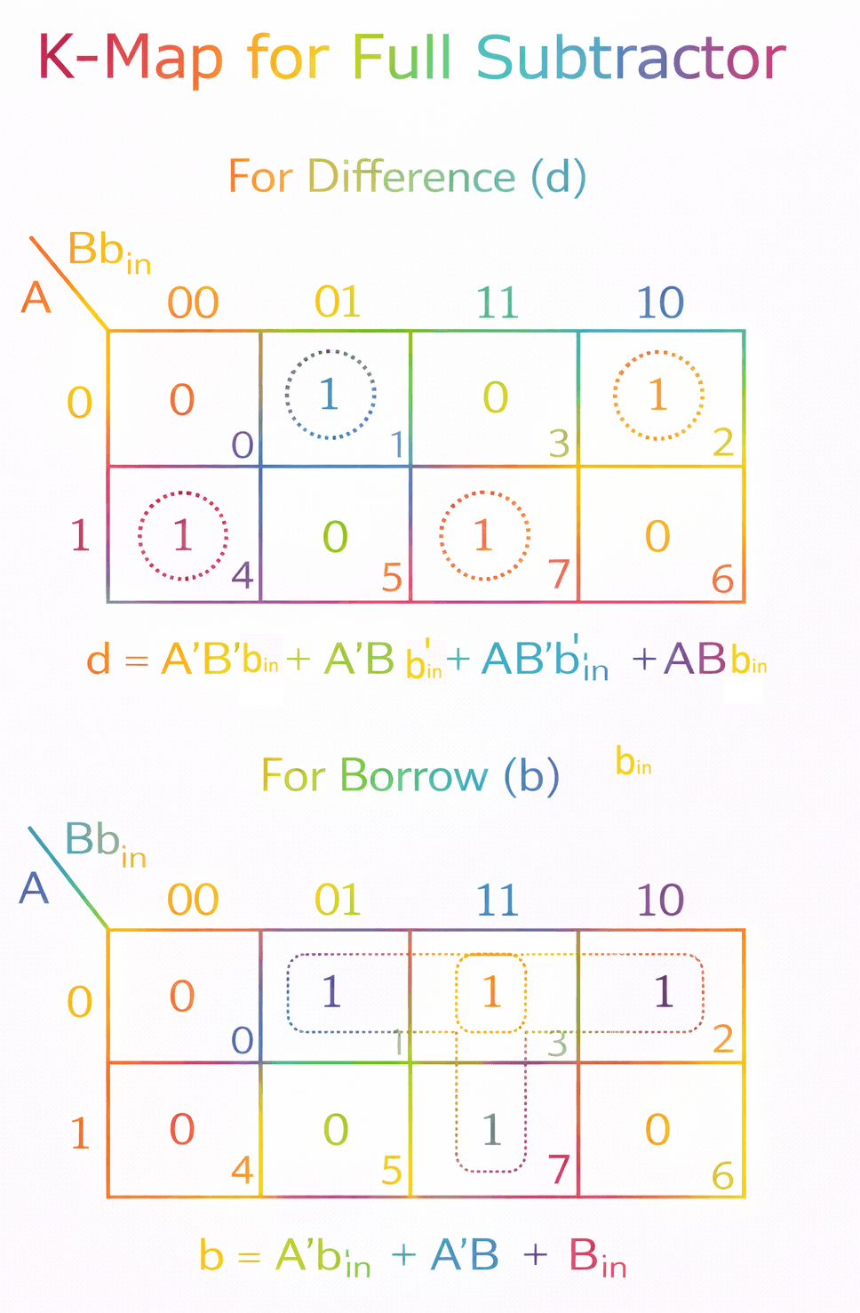
1) Serial Adder:
A Serial Adder performs binary addition one bit at a time using a single Full Adder, shift registers, and a flip-flop to store carry.
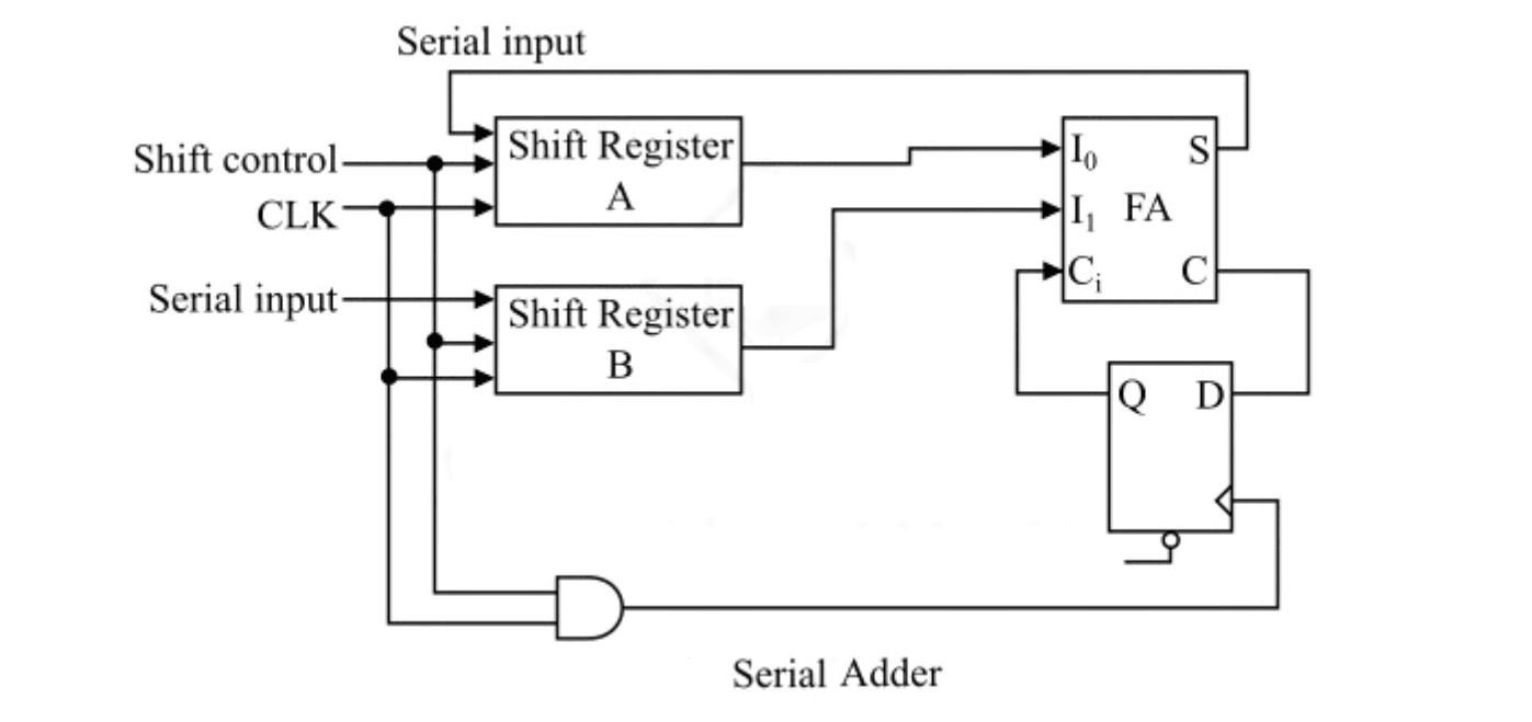
Operation:
- Bits are shifted from registers A and B.
- One pair of bits is added at a time along with previous carry.
- Sum is stored back in register.
- Process repeats for n clock pulses.
Example:
Add 1011 and 1101 (binary)
Step-by-step (LSB first):
1 + 1 = 0 carry 1
1 + 0 + 1 = 0 carry 1
0 + 1 + 1 = 0 carry 1
1 + 1 + 1 = 1 carry 1
Result = 11000
Features:
- Uses less hardware (only one Full Adder)
- Slower (requires multiple clock cycles)
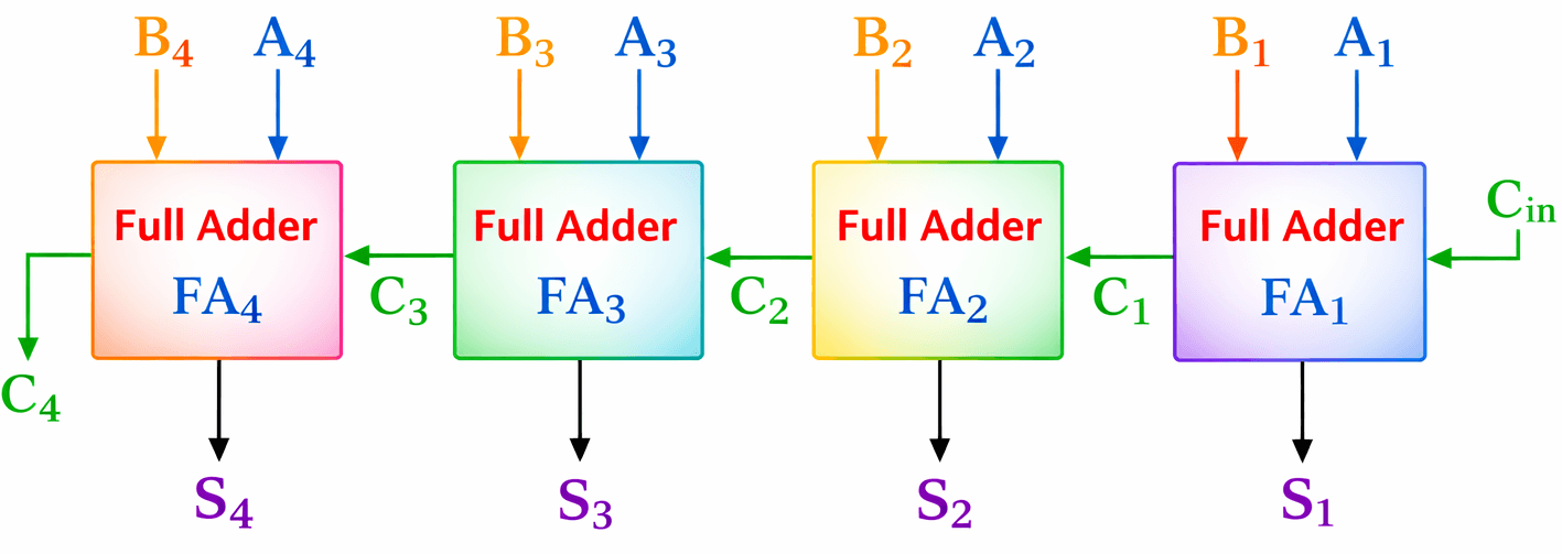
2) Parallel Adder:
A Parallel Adder adds all bits simultaneously using multiple Full Adders.
Each Full Adder handles one bit position.
Operation:
- All bits are applied at the same time.
- Carry from one Full Adder goes to the next stage.
- Entire addition is completed in one clock cycle.
Example:
Add 1011 and 1101
   1011
+  1101
-------
  11000
Features:
- Faster (single operation)
- Requires more hardware (multiple Full Adders)
Comparison:
- Serial Adder → Slow but economical.
- Parallel Adder → Fast but costlier.
১) Serial Adder:
Serial Adder এক সময়ে একটি করে bit যোগ করে। এতে একটি Full Adder, shift register এবং carry সংরক্ষণের জন্য flip-flop ব্যবহৃত হয়।
কার্যপ্রণালী:
- Register A ও B থেকে bit shift হয়ে আসে।
- প্রতি clock pulse-এ একটি bit যোগ হয়।
- Carry পরবর্তী যোগে ব্যবহৃত হয়।
- n clock pulse-এ n-bit যোগ সম্পন্ন হয়।
উদাহরণ:
1011 + 1101 = 11000
বৈশিষ্ট্য:
- কম hardware লাগে
- ধীরগতির (একাধিক clock লাগে)
২) Parallel Adder:
Parallel Adder একসাথে সব bit যোগ করে। এতে একাধিক Full Adder ব্যবহৃত হয়।
কার্যপ্রণালী:
- সব input bit একসাথে দেওয়া হয়।
- Carry এক stage থেকে পরবর্তী stage-এ যায়।
- একবারেই যোগ সম্পন্ন হয়।
উদাহরণ:
1011 + 1101 = 11000
বৈশিষ্ট্য:
- দ্রুত
- বেশি hardware প্রয়োজন
তুলনা:
- Serial Adder → ধীর কিন্তু সাশ্রয়ী
- Parallel Adder → দ্রুত কিন্তু ব্যয়বহুল
Combinational Circuits: Encoder, Decoder
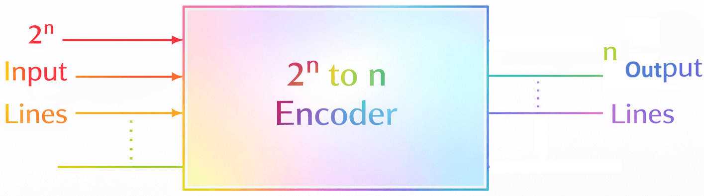
Types of Encoders
- 4 to 2 Encoder
- 8 to 3 Encoder (Octal Encoder)
- Decimal to BCD Encoder
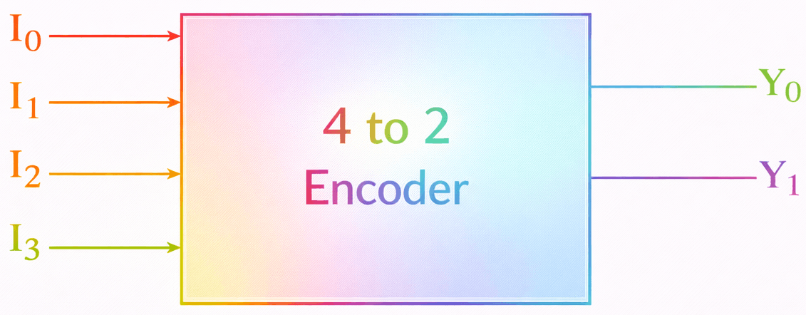
The working of a 4 to 2 Encoder for different input combinations is described in the following truth table −
| Inputs | Outputs | ||||
|---|---|---|---|---|---|
| I3 | I2 | I1 | I0 | Y1 | Y0 |
| 0 | 0 | 0 | 1 | 0 | 0 |
| 0 | 0 | 1 | 0 | 0 | 1 |
| 0 | 1 | 0 | 0 | 1 | 0 |
| 1 | 0 | 0 | 0 | 1 | 1 |
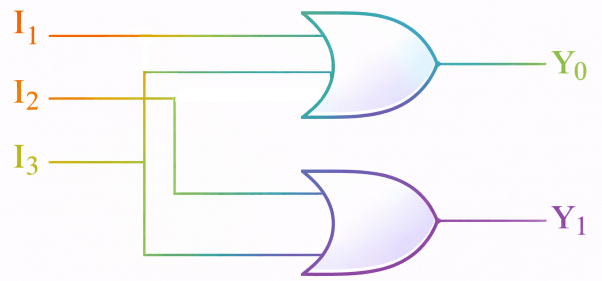
From this truth table, we can derive:
Y0=I1+I3
Y1=I2+I3
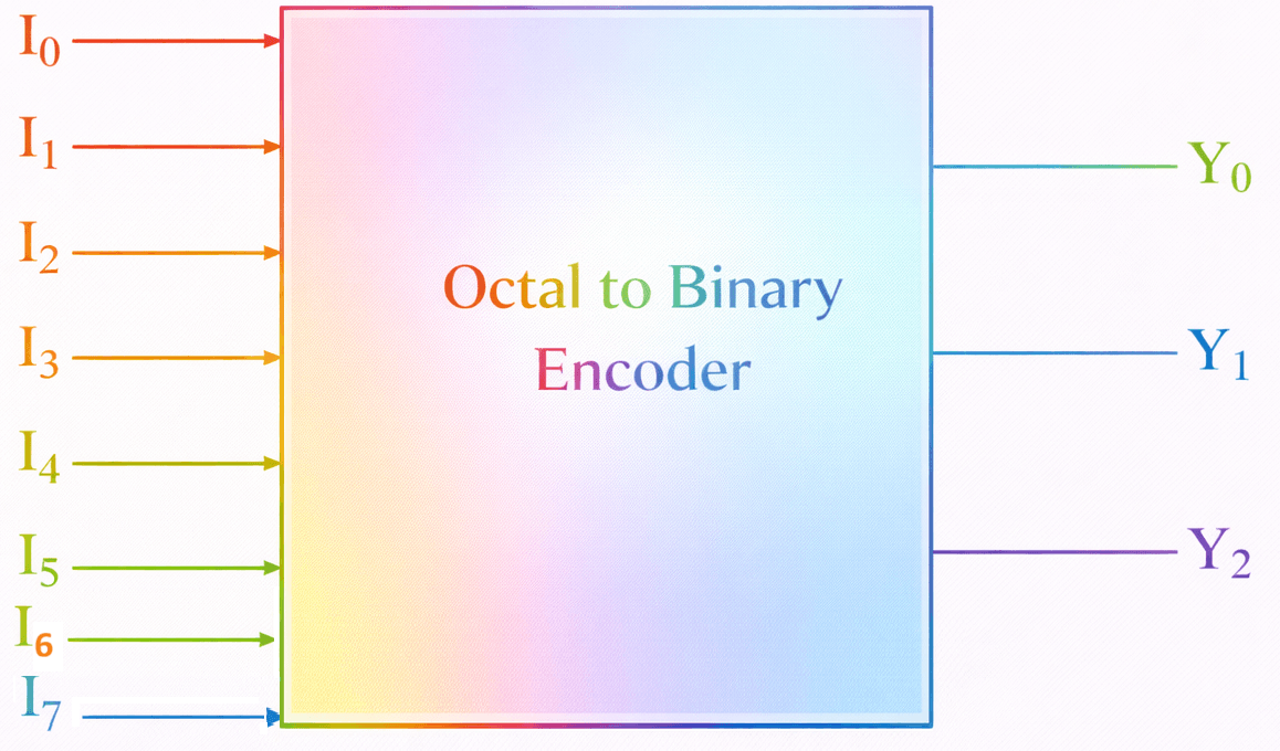
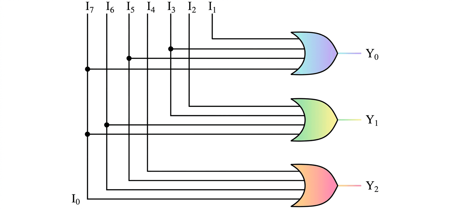
The following truth table describes the working of an octal to binary encoder −
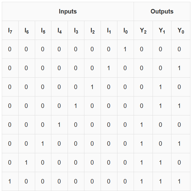
From this truth table, we can write the Boolean expression for the outputs of the octal to binary encoder as follows.
Y0 = I1 + I3 + I5 + I7
Y1 = I2 + I3 + I6 + I7
Y2 = I4 + I5 + I6 + I7
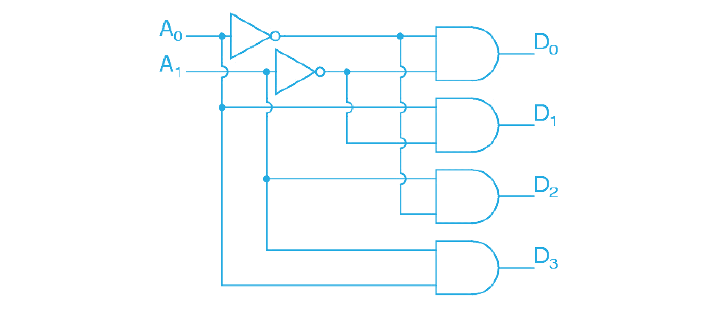
The truth table describing the working of the decimal to BCD encoder is −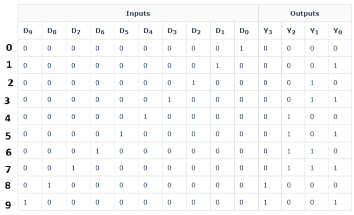
From the given truth table, the Boolean expressions for the decimal-to-BCD encoder can be written as follows:
Y0 = D1 + D3 + D5 + D7 + D9
Y1 = D2 + D3 + D6 + D7
Y2 = D4 + D5 + D6 + D7
Y3 = D8 + D9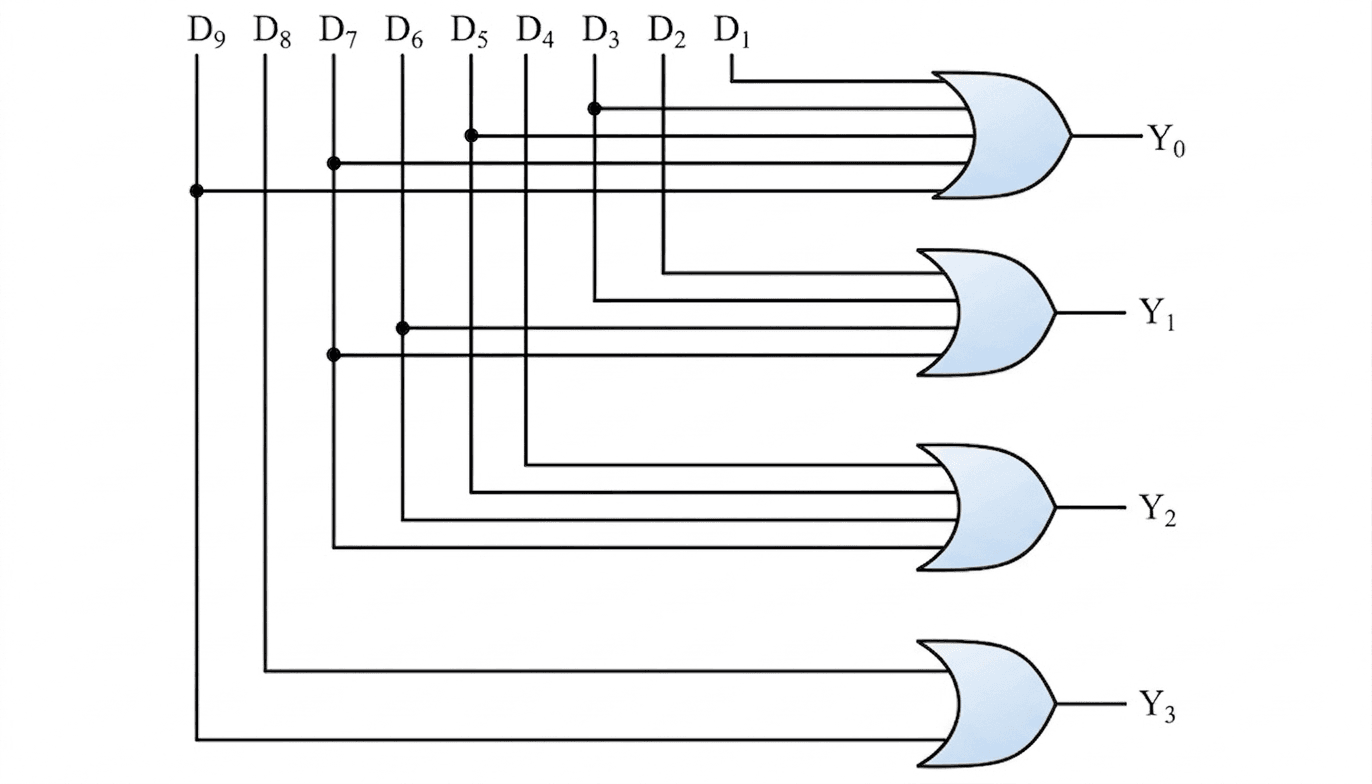
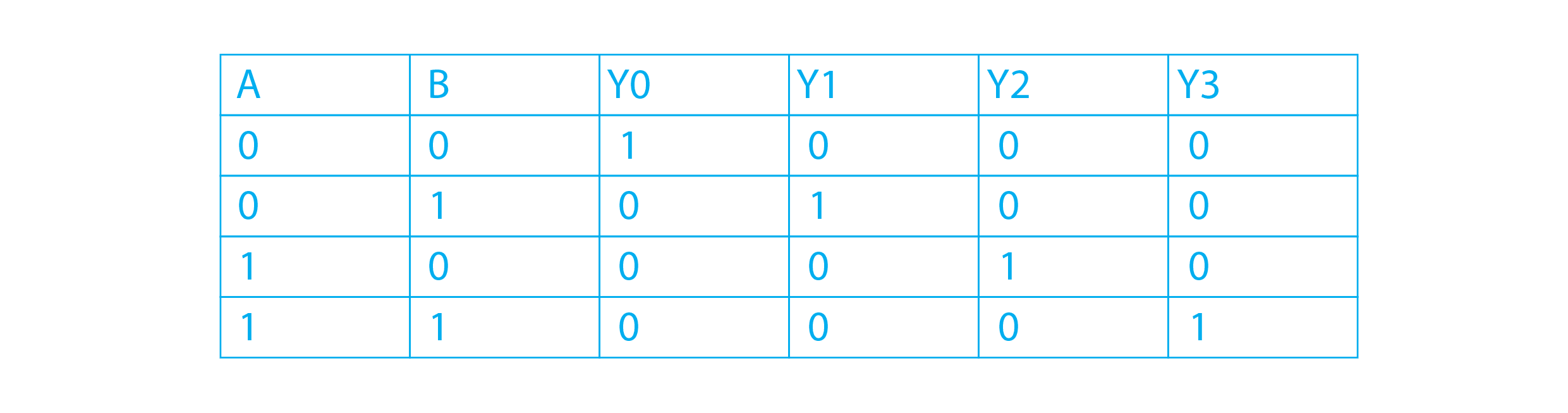
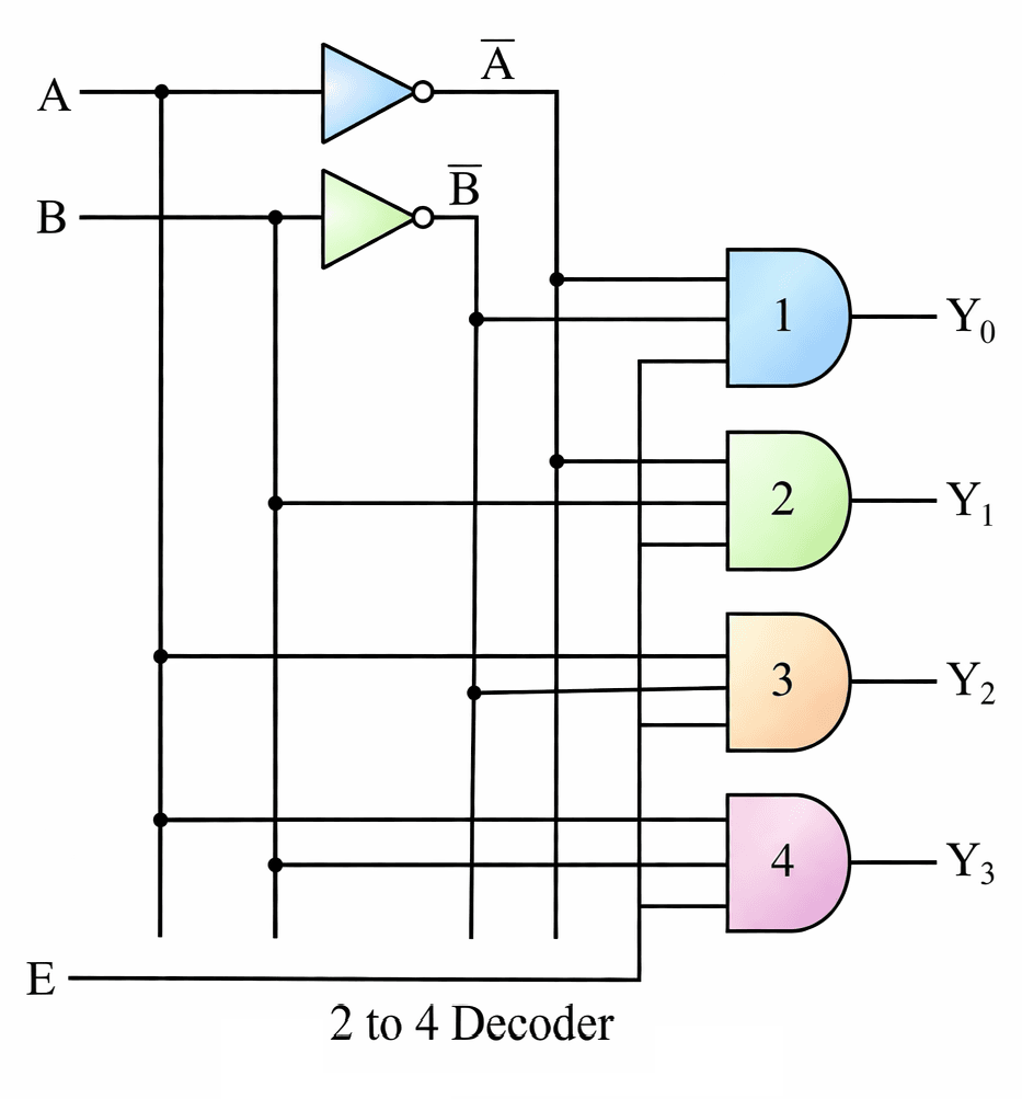
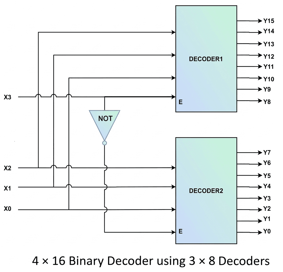
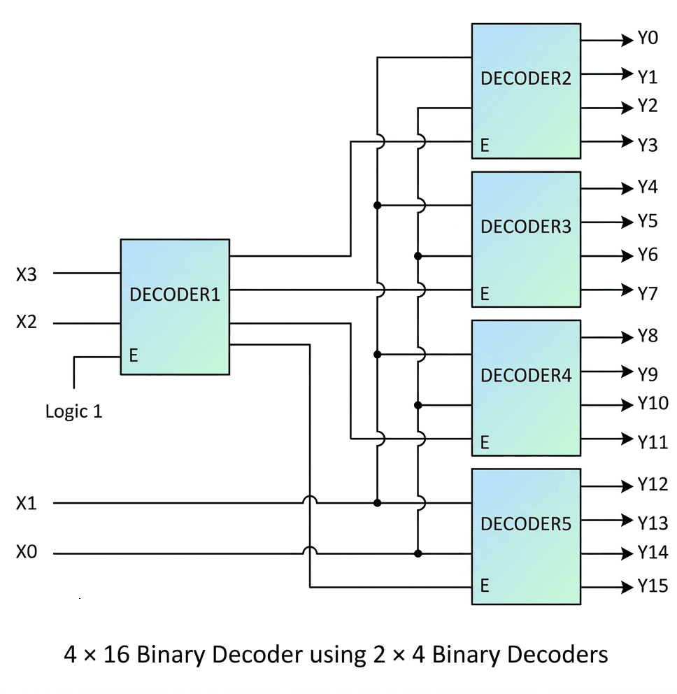
- Enable Input: It has an enable input E. When E = 1, the decoder works; when E = 0, all outputs are 0.
- Working: For each input combination of A and B, only one output becomes active.
| Inputs | Outputs | |||||
|---|---|---|---|---|---|---|
| E | A | B | Y3 | Y2 | Y1 | Y0 |
| 0 | X | X | 0 | 0 | 0 | 0 |
| 1 | 0 | 0 | 0 | 0 | 0 | 1 |
| 1 | 0 | 1 | 0 | 0 | 1 | 0 |
| 1 | 1 | 0 | 0 | 1 | 0 | 0 |
| 1 | 1 | 1 | 1 | 0 | 0 | 0 |
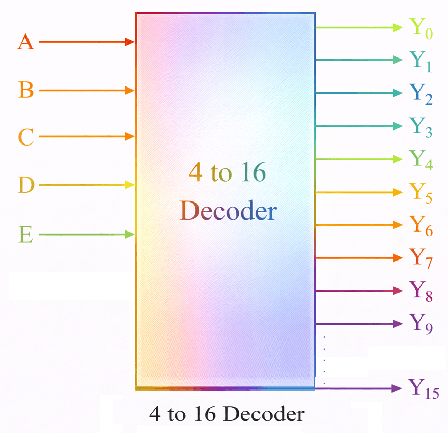
| Inputs | Output | ||||
|---|---|---|---|---|---|
| E | A | B | C | D | |
| 0 | X | X | X | X | 0 |
| 1 | 0 | 0 | 0 | 0 | Y0 |
| 1 | 0 | 0 | 0 | 1 | Y1 |
| 1 | 0 | 0 | 1 | 0 | Y2 |
| 1 | 0 | 0 | 1 | 1 | Y3 |
| 1 | 0 | 1 | 0 | 0 | Y4 |
| 1 | 0 | 1 | 0 | 1 | Y5 |
| 1 | 0 | 1 | 1 | 0 | Y6 |
| 1 | 0 | 1 | 1 | 1 | Y7 |
| 1 | 1 | 0 | 0 | 0 | Y8 |
| 1 | 1 | 0 | 0 | 1 | Y9 |
| 1 | 1 | 0 | 1 | 0 | Y10 |
| 1 | 1 | 0 | 1 | 1 | Y11 |
| 1 | 1 | 1 | 0 | 0 | Y12 |
| 1 | 1 | 1 | 0 | 1 | Y13 |
| 1 | 1 | 1 | 1 | 0 | Y14 |
| 1 | 1 | 1 | 1 | 1 | Y15 |
Details Truth Table: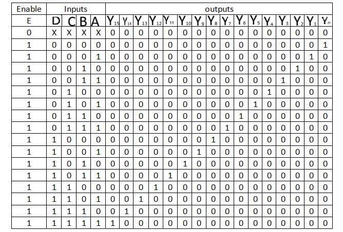
Y0 = E A’ B’ C’ D’
Y1 = E A’ B’ C’ D
Y2 = E A’ B’ C D’
Y3 = E A’ B’ C D
Y4 = E A’ B C’ D’
Y5 = E A’ B C’ D
Y6 = E A’ B C D’
Y7 = E A’ B C D
Y8 = E A B’ C’ D’
Y9 = E A B’ C’ D
Y10 = E A B’ C D’
Y11 = E A B’ C D
Y12 = E A B C’ D’
Y13 = E A B C’ D
Y14 = E A B C D’
Y15 = E A B C D
| Decimal | A | B | Cin | S | Cout |
|---|---|---|---|---|---|
| 0 | 0 | 0 | 0 | 0 | 0 |
| 1 | 0 | 0 | 1 | 1 | 0 |
| 2 | 0 | 1 | 0 | 1 | 0 |
| 3 | 0 | 1 | 1 | 0 | 1 |
| 4 | 1 | 0 | 0 | 1 | 0 |
| 5 | 1 | 0 | 1 | 0 | 1 |
| 6 | 1 | 1 | 0 | 0 | 1 |
| 7 | 1 | 1 | 1 | 1 | 1 |
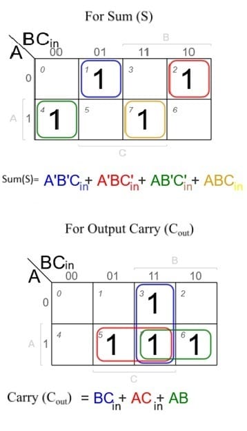
Sum =∑ (1,2,4,7)
Carry = ∑(3,5,6,7)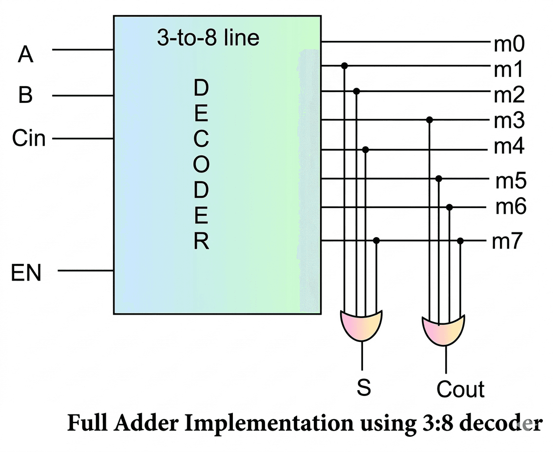
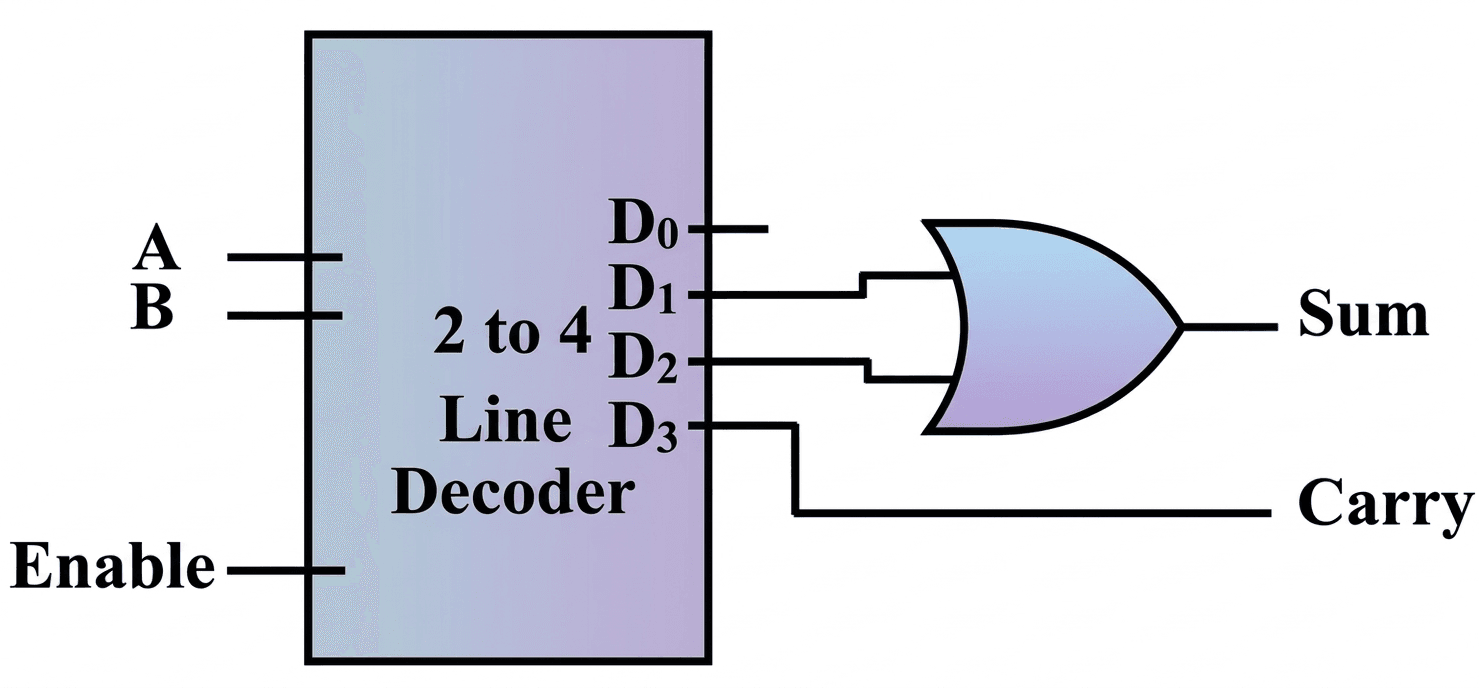
| Inputs | Outputs | |||||
|---|---|---|---|---|---|---|
| E | A | B | D3 | D2 | D1 | D0 |
| 0 | X | X | 0 | 0 | 0 | 0 |
| 1 | 0 | 0 | 0 | 0 | 0 | 1 |
| 1 | 0 | 1 | 0 | 0 | 1 | 0 |
| 1 | 1 | 0 | 0 | 1 | 0 | 0 |
| 1 | 1 | 1 | 1 | 0 | 0 | 0 |
Combinational Circuit: Multiplexer & Demultiplexer
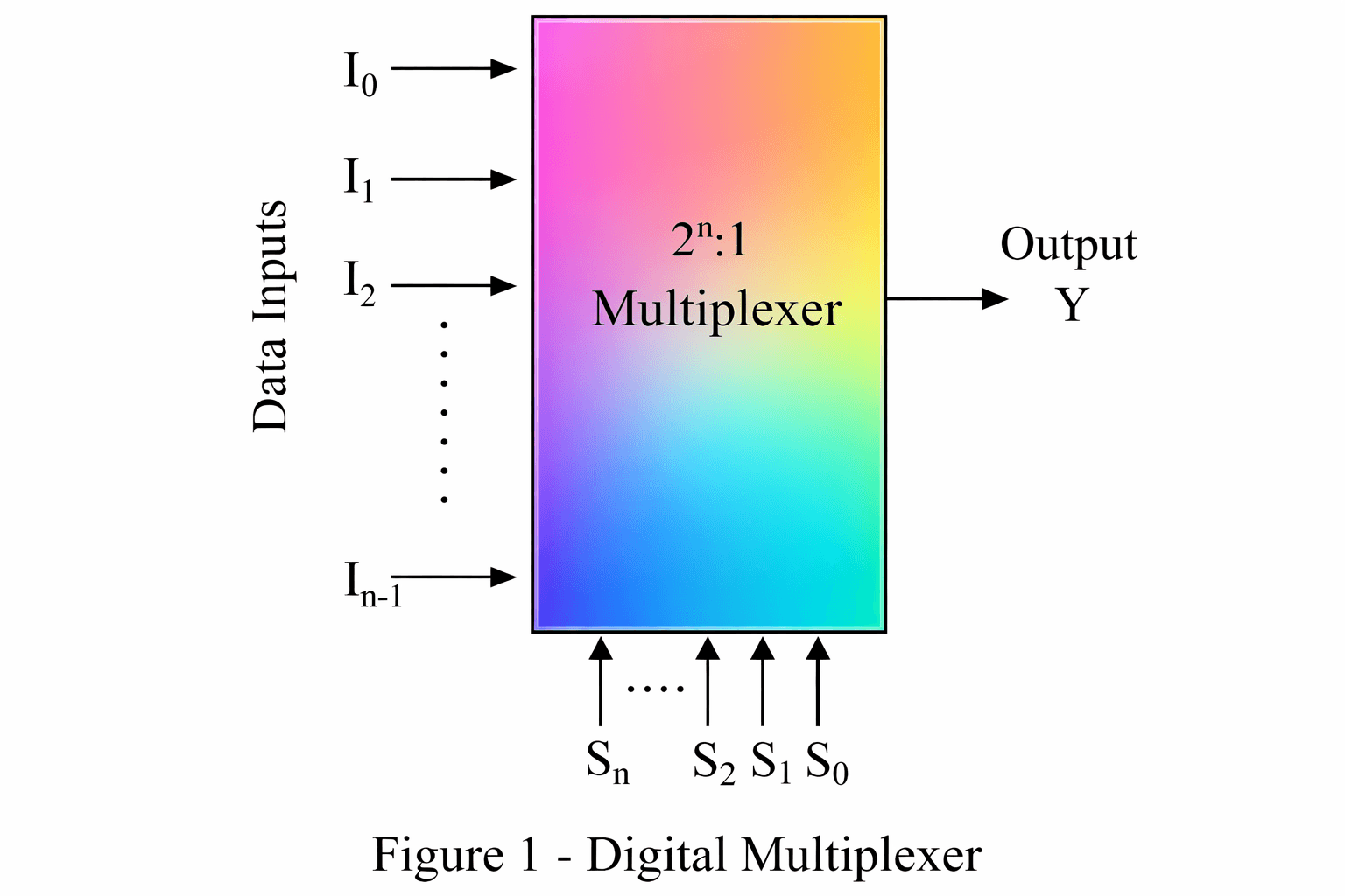
A 2 × 1 multiplexer is a basic combinational logic circuit that has two input lines (I₀, I₁), one select line (S), and one output line (Y).
- Function: It selects one of the two input signals and sends it to the output.
- Select Line: The digital value applied to S determines which input is selected.
Select Line (S) Output (Y) 0 I0 1 I1 - Application: It is used to connect two 1-bit data sources to a single output line.
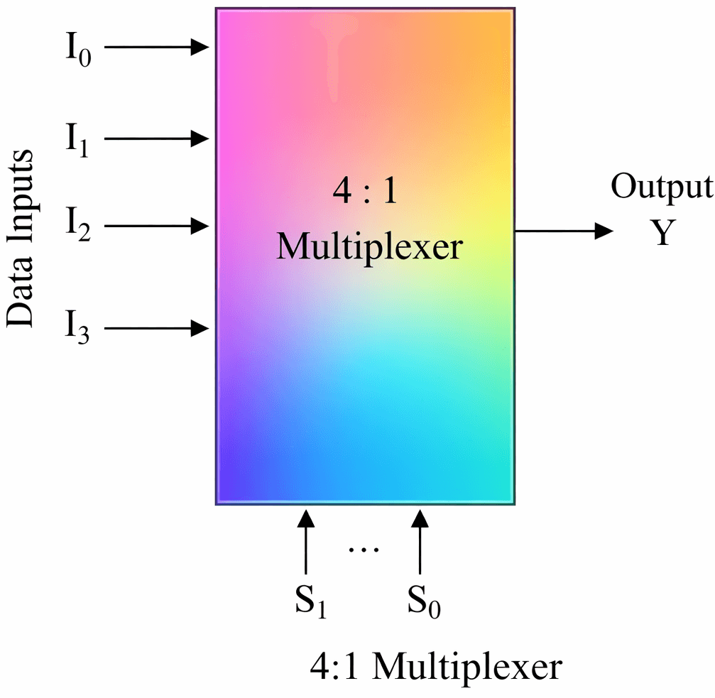
A 4 × 1 multiplexer is a digital circuit that has four input lines (I₀, I₁, I₂, I₃), two select lines (S₁, S₀), and one output line (Y).
- Function: It selects one of the four inputs and sends it to the output.
- Select Lines: The combination of S₁ and S₀ determines which input is selected.
Selection Lines Output S1 S0 Y 0 0 I0 0 1 I1 1 0 I2 1 1 I3
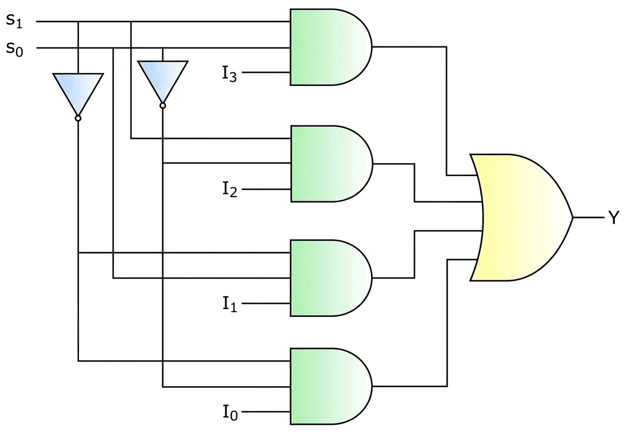
- Boolean Expression:
Y = S₁’ S₀’ I₀ + S₁’ S₀ I₁ + S₁ S₀’ I₂ + S₁ S₀ I₃
Implementation: It can be implemented using NOT gates, AND gates, and OR gate.
An 8 × 1 multiplexer is a digital circuit that has eight input lines (I₀ to I₇), three select lines (S₂, S₁, S₀), and one output line (Y).
- Function: It selects one of the eight inputs and forwards it to the output.
- Select Lines: The combination of S₂, S₁, S₀ determines which input is selected.
| Selection Inputs | Output | ||
|---|---|---|---|
| S2 | S1 | S0 | Y |
| 0 | 0 | 0 | I0 |
| 0 | 0 | 1 | I1 |
| 0 | 1 | 0 | I2 |
| 0 | 1 | 1 | I3 |
| 1 | 0 | 0 | I4 |
| 1 | 0 | 1 | I5 |
| 1 | 1 | 0 | I6 |
| 1 | 1 | 1 | I7 |
- Boolean Expression:
Y = S₂’S₁’S₀’I₀ + S₂’S₁’S₀I₁ + S₂’S₁S₀’I₂ + S₂’S₁S₀I₃ + S₂S₁’S₀’I₄ + S₂S₁’S₀I₅ + S₂S₁S₀’I₆ + S₂S₁S₀I₇ - Implementation: It can be implemented using NOT gates, AND gates, and OR gate.

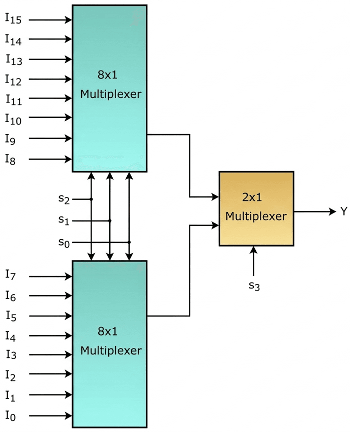
A 16 × 1 multiplexer is a digital circuit that has 16 input lines (I₀ to I₁₅), 4 select lines (S₃, S₂, S₁, S₀), and one output (Y).
- Function: It selects one of the 16 inputs and sends it to the output.
- Construction: It can be implemented using two 8 × 1 multiplexers (first stage) and one 2 × 1 multiplexer (second stage).
- Working:
The select lines S₂, S₁, S₀ are applied to both 8×1 multiplexers.
Upper 8×1 handles inputs I₈ to I₁₅ and lower 8×1 handles I₀ to I₇.
Their outputs are given to a 2×1 multiplexer. - Final Selection:
If S₃ = 0 → Output comes from inputs I₀ to I₇
If S₃ = 1 → Output comes from inputs I₈ to I₁₅
| Selection Inputs | Output | |||
|---|---|---|---|---|
| S3 | S2 | S1 | S0 | Y |
| 0 | 0 | 0 | 0 | I0 |
| 0 | 0 | 0 | 1 | I1 |
| 0 | 0 | 1 | 0 | I2 |
| 0 | 0 | 1 | 1 | I3 |
| 0 | 1 | 0 | 0 | I4 |
| 0 | 1 | 0 | 1 | I5 |
| 0 | 1 | 1 | 0 | I6 |
| 0 | 1 | 1 | 1 | I7 |
| 1 | 0 | 0 | 0 | I8 |
| 1 | 0 | 0 | 1 | I9 |
| 1 | 0 | 1 | 0 | I10 |
| 1 | 0 | 1 | 1 | I11 |
| 1 | 1 | 0 | 0 | I12 |
| 1 | 1 | 0 | 1 | I13 |
| 1 | 1 | 1 | 0 | I14 |
| 1 | 1 | 1 | 1 | I15 |
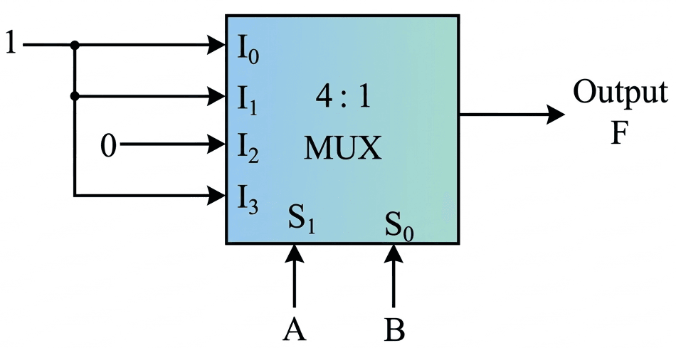
The truth table of the 4:1 multiplexer for the given logic function is as follows
| Select Lines | Output | |
|---|---|---|
| S1 = A | S0 = B | Y |
| 0 | 0 | 1 |
| 0 | 1 | 1 |
| 1 | 0 | 0 |
| 1 | 1 | 1 |
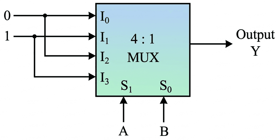
The truth table of the 4:1 multiplexer for the given logic function is as follows,
| Select Lines | Output | |
|---|---|---|
| S1 = A | S0 = B | Y |
| 0 | 0 | 0 |
| 0 | 1 | 1 |
| 1 | 0 | 0 |
| 1 | 1 | 1 |
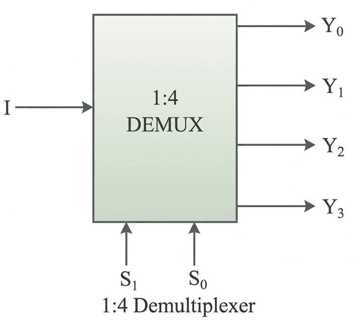
A 1 × 4 demultiplexer is a combinational circuit that has 1 input (I), 2 select lines (S₁, S₀), and 4 output lines (Y₀ to Y₃).
Function: It transfers the input signal to one of the four outputs based on select lines.
Select Lines: The combination of S₁ and S₀ determines which output will receive the input.
Working (Truth Table):
| Select Line | Outputs | ||||
|---|---|---|---|---|---|
| S1 | S0 | Y3 | Y2 | Y1 | Y0 |
| 0 | 0 | 0 | 0 | 0 | I |
| 0 | 1 | 0 | 0 | I | 0 |
| 1 | 0 | 0 | I | 0 | 0 |
| 1 | 1 | I | 0 | 0 | 0 |
Boolean Expressions:
Y₀ = S₁’ S₀’ I
Y₁ = S₁’ S₀ I
Y₂ = S₁ S₀’ I
Y₃ = S₁ S₀ I
Implementation: It can be implemented using AND gates and NOT gates.
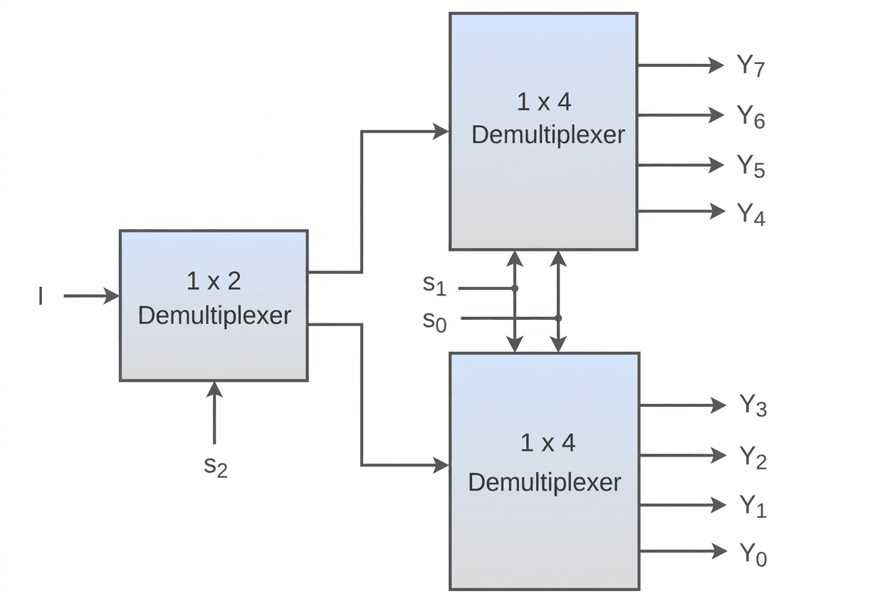
A 1 × 8 demultiplexer can be implemented by using two 1 × 4 demultiplexers and one 1 × 2 demultiplexer.
Structure: A 1 × 8 demultiplexer has 1 input (I), 3 select lines (S2, S1, S0), and 8 outputs (Y0 to Y7).
Construction: One 1 × 2 demultiplexer is used in the first stage and two 1 × 4 demultiplexers are used in the second stage.
First Stage: The input I is given to the 1 × 2 demultiplexer. The select line S2 controls which second-stage demultiplexer will be activated.
Second Stage: The common select lines S1 and S0 are applied to both 1 × 4 demultiplexers. These lines decide the exact output line.
Working:
If S2 = 0, one of the outputs Y0 to Y3 becomes equal to input I based on S1 and S0.
If S2 = 1, one of the outputs Y4 to Y7 becomes equal to input I based on S1 and S0.
Output Distribution: The lower 1 × 4 demultiplexer produces outputs Y0 to Y3, and the upper 1 × 4 demultiplexer produces outputs Y4 to Y7.
Truth Table: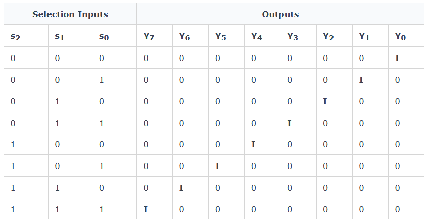
Introduction to Sequential Circuit,
A Sequential Circuit is a digital logic circuit in which the output depends not only on the present inputs but also on the past history (previous outputs) of the system.
Basic Concept:
Unlike combinational circuits (which depend only on current inputs), sequential circuits have memory elements that store previous states. Because of this, the circuit behavior changes over time based on input sequence.
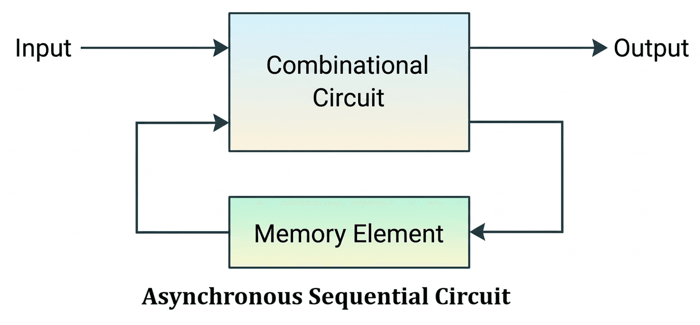
Block Structure:
A sequential circuit consists of:
- Combinational Logic Circuit → Performs logical operations on inputs.
- Memory Element → Stores previous output (state).
- Feedback Path → Connects output back to input.
Working Principle:
- The input is processed by combinational logic.
- The output is stored in memory (flip-flops).
- This stored value is fed back and used in the next operation.
- Thus, output = present input + past state.
Main Components:
- Logic Gates: AND, OR, NOT etc. perform logical operations.
- Flip-Flops: Store binary information (memory).
- Clock Signal: Controls timing of operations (in synchronous circuits).
- Feedback Mechanism: Maintains system history..
Examples:
- Flip-Flops: Store 1-bit data.
- Counters: Count pulses (e.g., binary counter).
- Registers: Store multi-bit data.
Characteristics:
- Has memory capability.
- Output depends on input sequence.
- Requires feedback path.
- Used in real-time systems and control systems.
Application:
- Digital clocks
- Computers (CPU registers, memory units)
- Control systems
- Communication systems
Sequential Circuit হলো এমন একটি digital circuit যার output নির্ভর করে বর্তমান input এবং পূর্বের output (memory)-এর উপর।
মূল ধারণা:
Combinational circuit শুধুমাত্র বর্তমান input-এর উপর নির্ভর করে, কিন্তু sequential circuit-এ memory element থাকে যা পূর্বের state সংরক্ষণ করে। তাই input-এর sequence অনুযায়ী output পরিবর্তিত হয়।
Block Structure:
- Combinational Logic Circuit: Input-এর উপর logical operation করে।
- Memory Element: পূর্বের output সংরক্ষণ করে (flip-flop)।
- Feedback Path: Output আবার input-এ পাঠায়।
কাজ করার পদ্ধতি:
- Input combinational logic-এ প্রবেশ করে।
- Output memory-তে সংরক্ষণ হয়।
- এই stored value আবার future input-এ ব্যবহৃত হয়।
- অতএব output = বর্তমান input + পূর্বের state
প্রধান উপাদান:
- Logic Gates: AND, OR, NOT gate data process করে।
- Flip-Flops: Memory হিসেবে কাজ করে।
- Clock Signal: Timing control করে (synchronous circuit-এ)।
- Feedback: System-এর history ধরে রাখে।
উদাহরণ:
- Flip-Flop: 1-bit data সংরক্ষণ করে।
- Counter: Pulse গণনা করে।
- Register: একাধিক bit data সংরক্ষণ করে।
বৈশিষ্ট্য:
- Memory থাকে
- Output input-এর sequence-এর উপর নির্ভর করে
- Feedback path থাকে
- Real-time system-এ ব্যবহৃত হয়
ব্যবহার:
- Digital clock
- Computer (CPU register, memory)
- Control system
- Communication system

Latch in Digital Electronics
A latch is an asynchronous sequential circuit that can store 1-bit of information. It is a fundamental memory element used in digital systems.
A latch has two stable states:
- Set (1)
- Reset (0)
Because of these two stable states, it is called a bistable multivibrator. The state of a latch changes according to the input applied.
Important Feature:
Latches do not use a clock signal, so they operate immediately when input changes.
Characteristics of Latch
- Stores 1-bit data (0 or 1).
- Uses feedback to maintain its state.
- Output depends directly on input changes.
- Works without synchronization (clock).
Types of Latches
- SR Latch
- JK Latch
- D Latch
- T Latch
1. SR Latch (Set-Reset)
SR latch has two inputs:
- S → Set
- R → Reset
Operation:
- S = 1 → Q = 1 (Set)
- R = 1 → Q = 0 (Reset)
- S = R = 1 → Forbidden state
Truth Table:
S   R   Q   Q'   Comment
0   0   Q   Q'   No change
0   1   0   1    Reset
1   0   1   0    Set
1   1   X   X    Forbidden
2. JK Latch
JK latch is an improved version of SR latch (no forbidden state).
- J → Set
- K → Reset
Special Case:
- J = K = 1 → Toggle
Truth Table:
J   K   Q   Q'   Comment
0   0   Q   Q'   No change
0   1   0   1    Reset
1   0   1   0    Set
1   1   Q'  Q    Toggle
3. D Latch (Data Latch)
Inputs:
- D → Data
- E → Enable
Working:
- E = 1 → Output follows input D
- E = 0 → Output remains unchanged
Truth Table:
D   E   Q   Q'   Comment
0   0   Q   Q'   No change
0   1   0   1    Reset
1   0   Q   Q'   No change
1   1   1   0    Set
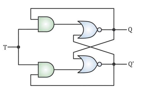
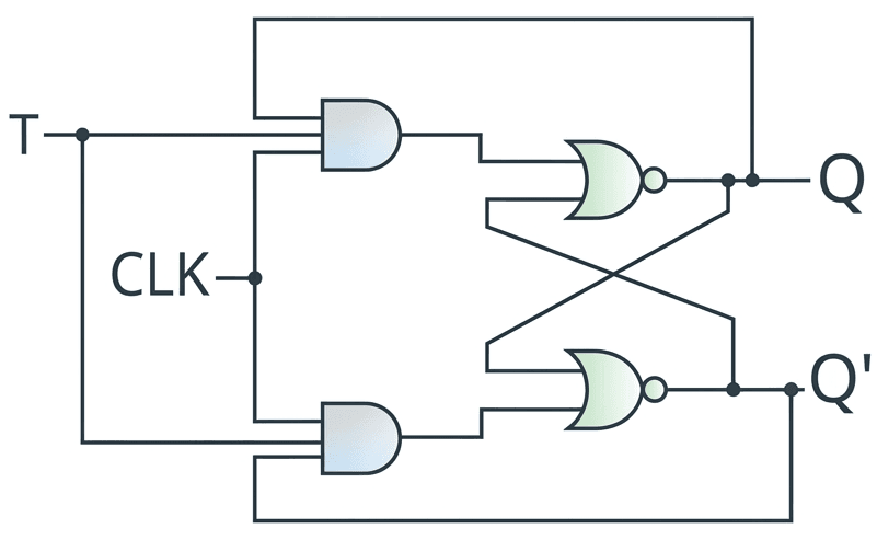
4. T Latch (Toggle Latch)
Input:
- T → Toggle input
Working:
- T = 0 → No change
- T = 1 → Output toggles
Truth Table:
T   Q(t)   Q(t+1)
0    0       0
0    1       1
1    0       1
1    1       0
Applications of Latches
- Used as 1-bit memory element
- Used in registers for data storage
- Used to design flip-flops
- Used in buffering and communication systems
Conclusion:
Latch is a simple and fast memory device used in digital circuits where immediate response is required without clock control.
Latch (ডিজিটাল ইলেকট্রনিক্সে)
Latch হলো একটি asynchronous sequential circuit যা ১-bit data সংরক্ষণ করতে পারে এবং এটি digital system-এর একটি মৌলিক memory element।
এটির দুটি স্থিতিশীল অবস্থা আছে:
- Set (1)
- Reset (0)
তাই এটিকে bistable multivibrator বলা হয়।
গুরুত্বপূর্ণ বৈশিষ্ট্য:
Latch-এ clock signal নেই, তাই input পরিবর্তন হলেই সাথে সাথে output পরিবর্তিত হয়।
বৈশিষ্ট্য
- ১-bit data সংরক্ষণ করে
- Feedback ব্যবহার করে state ধরে রাখে
- Input পরিবর্তনের সাথে output পরিবর্তিত হয়
- Clock ছাড়াই কাজ করে
প্রকারভেদ
- SR Latch
- JK Latch
- D Latch
- T Latch
1. SR Latch
S   R   Q   Q'   Comment
0   0   Q   Q'   No change
0   1   0   1    Reset
1   0   1   0    Set
1   1   X   X    Forbidden
2. JK Latch
J   K   Q   Q'   Comment
0   0   Q   Q'   No change
0   1   0   1    Reset
1   0   1   0    Set
1   1   Q'  Q    Toggle
3. D Latch
D   E   Q   Q'   Comment
0   0   Q   Q'   No change
0   1   0   1    Reset
1   0   Q   Q'   No change
1   1   1   0    Set
4. T Latch
T   Q(t)   Q(t+1)
0    0       0
0    1       1
1    0       1
1    1       0
ব্যবহার
- ১-bit memory হিসেবে
- Register design-এ
- Flip-flop তৈরিতে
- Communication system-এ data buffer হিসেবে
উপসংহার:
Latch একটি দ্রুত এবং সহজ memory device যা clock ছাড়া কাজ করে এবং digital circuit-এ ব্যাপকভাবে ব্যবহৃত হয়।
Sequential Circuit: Flip Flop
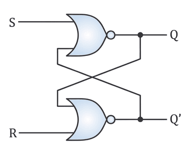
The S-R (Set-Reset) flip-flop is the simplest type of flip-flop. It has two inputs S (Set) and R (Reset) and two outputs Q and Q’.
- Set Condition: When S = 1 and R = 0, output Q = 1 (Set state).
- Reset Condition: When S = 0 and R = 1, output Q = 0 (Reset state).
- No Change: When S = 0 and R = 0, output remains unchanged.
- Invalid State: When S = 1 and R = 1, output becomes undefined.
Characteristics Table of S-R Flip-Flop
| S | R | Q(t) | Q(t+1) |
|---|---|---|---|
| 0 | 0 | 0 | 0 |
| 0 | 0 | 1 | 1 |
| 0 | 1 | 0 | 0 |
| 0 | 1 | 1 | 0 |
| 1 | 0 | 0 | 1 |
| 1 | 0 | 1 | 1 |
| 1 | 1 | 0 | X |
| 1 | 1 | 1 | X |
Characteristic Equation:
Q(t+1) = S + R’Q(t)
Circuit Diagram: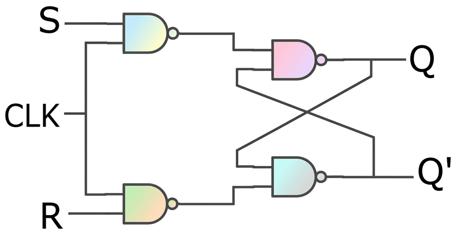
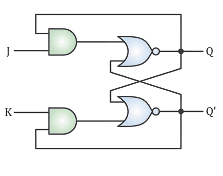
The J-K flip-flop is an improved version of the S-R flip-flop that eliminates the invalid state. It works based on clock signals.
- No Change: When J = 0 and K = 0, output remains unchanged.
- Reset: When J = 0 and K = 1, output Q = 0.
- Set: When J = 1 and K = 0, output Q = 1.
- Toggle: When J = 1 and K = 1, output toggles (0 → 1 or 1 → 0).
Working: Output changes only at the clock edge (positive or negative transition).
Characteristics:
| J | K | Q(t) | Q(t+1) |
|---|---|---|---|
| 0 | 0 | 0 | 0 |
| 0 | 0 | 1 | 1 |
| 0 | 1 | 0 | 0 |
| 0 | 1 | 1 | 0 |
| 1 | 0 | 0 | 1 |
| 1 | 0 | 1 | 1 |
| 1 | 1 | 0 | 1 |
| 1 | 1 | 1 | 0 |
Characteristic Equation:
Q(t+1) = JQ'(t) + K’Q(t)
Circuit Diagram: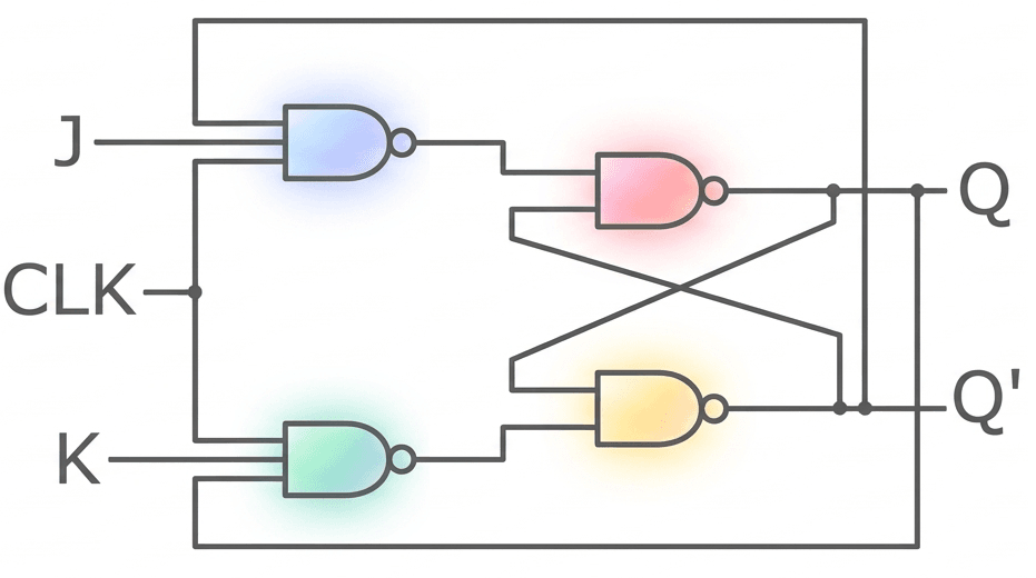
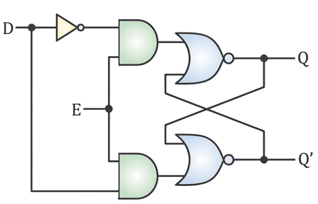
A D (Data) flip-flop is a sequential circuit where the output Q follows the input D at the clock edge.
Function: It stores the value of input D at the active clock transition.
Working: Output changes only at the clock edge (positive or negative).
Behavior: At clock edge → Q = D; otherwise, output remains unchanged.
Application: Used in shift registers and counters.
| D | Q |
|---|---|
| 0 | 0 |
| 1 | 1 |
Characteristic Equation:
Q(t+1) = D
Circuit Diagram: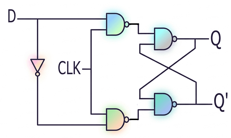
Previous Job QnS (Digital Logic Design)
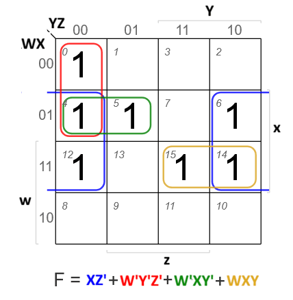
- 1Digital Logic DesignKmapSolve the following function using K-map. F (w, x, y, z)= ∑(0,4,5,6,12,14,15)CB, SO(IT), 22 | Senior Officer (IT)

- 2Digital Logic DesignKmapMake a boolean expression using Karnaugh map: ∑m = (3,5,7,9,11,13,14,15)CB, AE(IT)/AHME/SO, 21 | Bank

- 3Digital Logic DesignBasicDetermine whether the logical statement (P -> Q) -> (P' -> Q') is a tautology, contradiction, or contingency.ICB, AP, 26 | Others
- 4Digital Logic DesignBasicDescribe the important characteristics of digital IC's.CB, AME/AHE, 23 | Bank
- 5Digital Logic DesignBasicConstruct a Truth Table for a system that triggers an Alarm (Output 1) if: (Motion is Detected AND it is Night Time) OR (Panic Button is Pressed).Combined Bank, O(IT-22), 26 | Bank
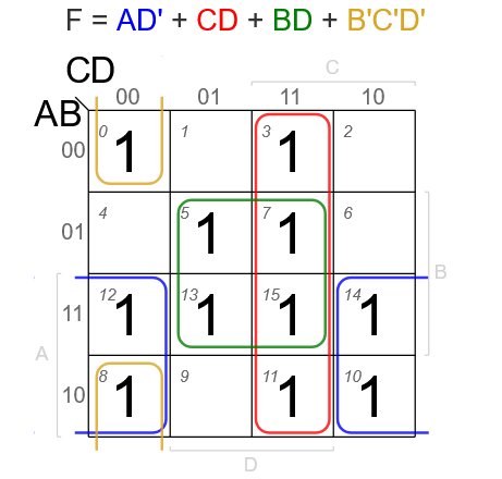
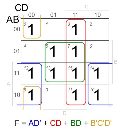
- 6Digital Logic DesignkmapSimplify the following boolean expression using 4 variable K-map F(A, B,C,D)=m(0,3,5,7,8,10,11,12,13,14,15).Combined Bank, AE(IT)/AME, 26 | Bank

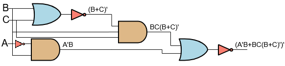
- 7Digital Logic DesignBasic GateDraw the logic circuit for the Boolean expression Q = (A'B + BC(B + C)')'. Find the value of Q when (A, B, C) = (1, 0, 1).CB, AE(IT)/AME, 24 | Bank
 (A'B+BC(B+C)')'
∘ Substitute the values A = 1, B = 0, C = 1 into the equation.
= (1'·0+0·1(0+1)')'
= (0·0+0·1(0+1)')'
= (0·0+0·1·1')'
= (0·0+0·1·0)'
= (0+0·1·0)'
= (0+0)'
= 0'
= 1
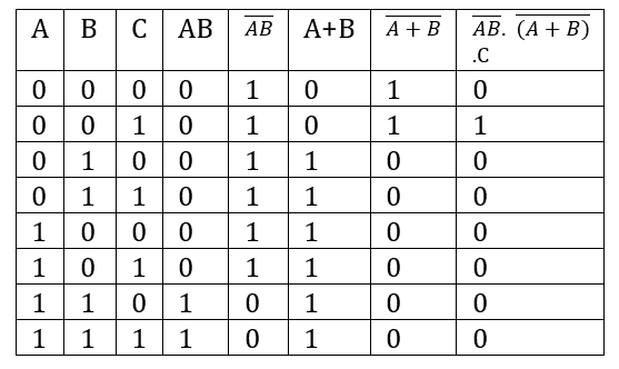
- 8Digital Logic DesignBasic GateGiven a logical function, find out the truth table of AB· (A+B).CBB, AD(ICT), 25 | Bangladesh Bank

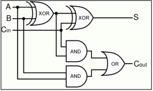
- 9Digital Logic DesignBasic GatesDraw the truth table from the follwoing circuit (2 bit input A,B full adder with carry bit Cin)
 Sonali Bank, ADA, 24 | Bank
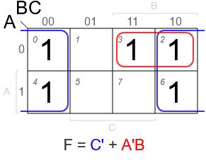
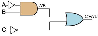
 - 10Digital Logic DesignBasic GatesSimplify the Boolean algebra: Q = C' + A'B + BC'(B' + C) and draw a logic circuit.Sonali Bank, ADA, 24 | Bank

Logic Circuit:

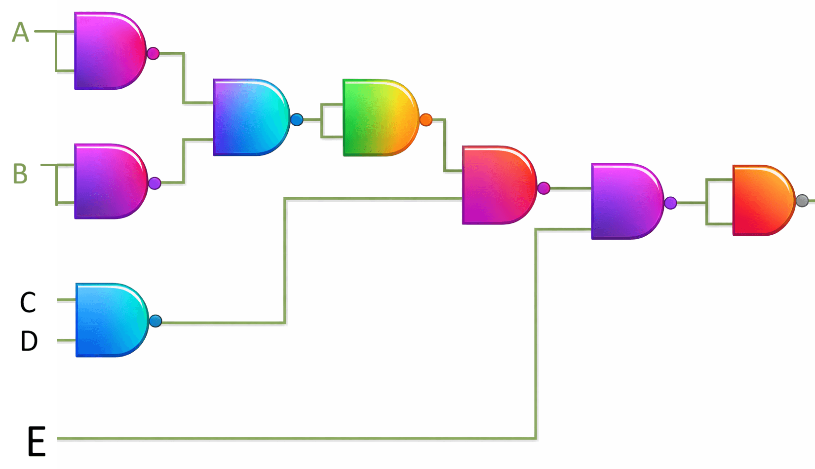
- 11Digital Logic DesignUniversal GateWhat is a Universal Gate? Prove that the NAND Gate is a Universal Gate.Combined Bank, AP-22, 26 | Bank
Universal Gate
A Universal Gate is a logic gate that can be used to implement any Boolean function (i.e., any logic circuit). If we can build the basic gates NOT, AND, and OR using only one type of gate, then that gate is called a universal gate.
Proof: NAND is a Universal Gate
To prove NAND is universal, we show that we can construct NOT, AND, and OR using only NAND gates.

Since we can build NOT, AND, and OR using only NAND gates, we can build any Boolean expression. Therefore, the NAND gate is a Universal Gate.
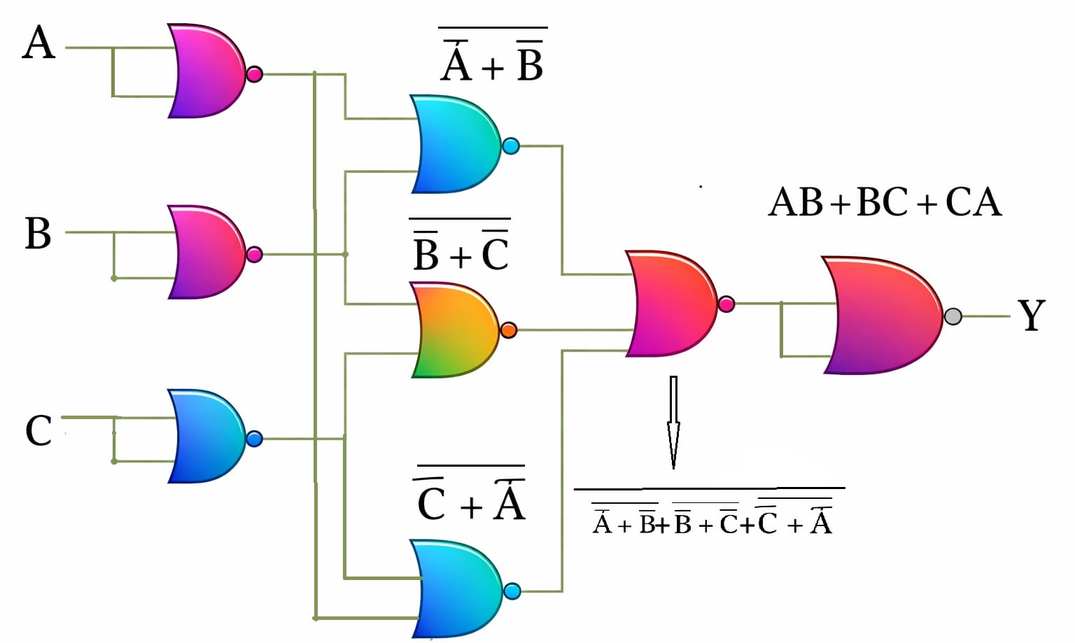
- 12Digital Logic DesignUniversal GateExplain how any Boolean function can be implemented using only universal gates.Combined Bank, O(IT-23), 26 | Bank
Universal gates are logic gates that can implement any Boolean function without using any other type of gate.
The two universal gates are:
- NAND Gate
- NOR Gate
Using only NAND gates or only NOR gates, all basic logic gates such as AND, OR, and NOT can be constructed. Since any Boolean function is built using these basic gates, any Boolean function can also be implemented using universal gates.
Implementation Using NAND Gate
1. NOT Gate using NAND
When both inputs of a NAND gate are connected together:
$$
Y=\overline{A\cdot A}=\overline{A}
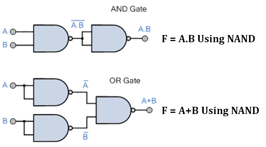
$$2. AND Gate using NAND
First NAND operation gives:
(A · B)'Applying another NAND as NOT operation:
$$
Y=\overline{\overline{A\cdot B}}=A\cdot B
$$3. OR Gate using NAND
Using De Morgan’s theorem:
$$
A+B=\overline{\overline{A}\cdot\overline{B}}
$$So OR gate can also be implemented using only NAND gates.
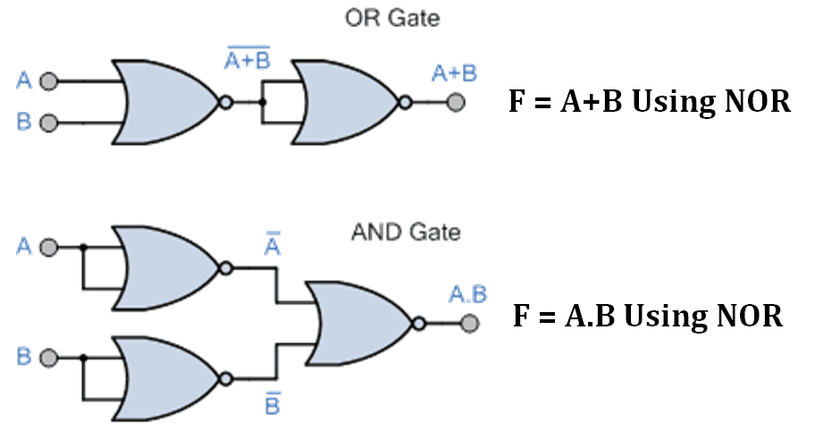
Implementation Using NOR Gate
1. NOT Gate using NOR
When both inputs are same:
$$
Y=\overline{A+A}=\overline{A}
$$2. OR Gate using NOR
First NOR operation gives:
(A + B)'Applying another NOR as NOT operation:
$$
Y=\overline{\overline{A+B}}=A+B
$$3. AND Gate using NOR
Using De Morgan’s theorem:
$$
A\cdot B=\overline{\overline{A}+\overline{B}}
$$Since NAND and NOR gates can create all basic logic gates, and all Boolean functions are formed using basic gates, any Boolean function can be implemented using only NAND gates or only NOR gates.


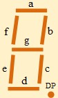
- 13Digital Logic DesignFor 7 segments display the input is abcdefg. When a decimal digit or value is display then its equivalent segment is high.
(i) Find out the logical expression in Sum of product for 2bit binary input.Rupali, ANE, 21 |
i) For 2 bit binary, we can find 00, 01, 10, 11 and the equivalent decimal value is 0,1,2,3.
Now, For Binary= 00 (Decimal= 0)= abcdef is high
For Binary= 01 (Decimal=1)= bc is high
For Binary= 10 (Decimal=2) = abged is high For
Binary=11 (Decimal=3)= abgcd is high
- 14Digital Logic Design(ii) Draw logic circuit for 2to4 Line decoder/Demulltiplexer.Rupali, ANE, 21 |
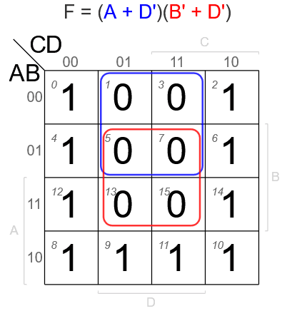
- 15Digital Logic DesignSimplify the Boolean equation using K-map: F(A,B,C,D) = Σ(0,3,5,7,8,10,11,12,13,14,15).BB, AME/AE(IT), 26 | Bangladesh Bank


 (A'B+BC(B+C)')'