Previous Job QnS (Digital Logic Design)
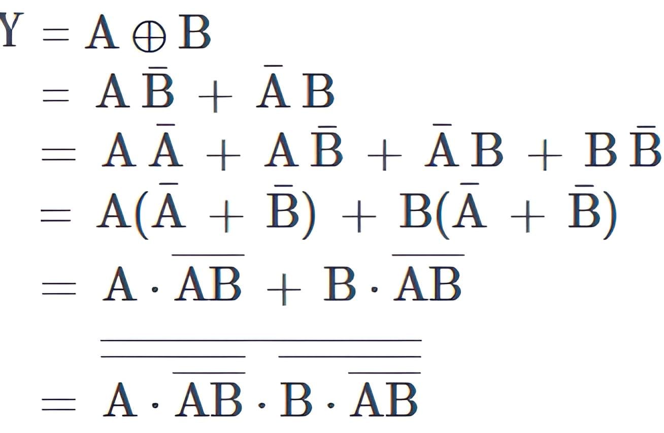
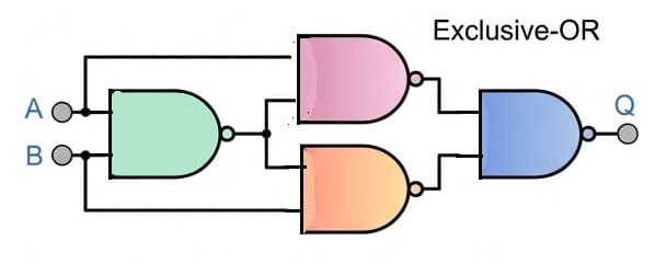
- ☆1Digital Logic DesignUniversal GateDraw the circuit schematic diagrams to build an Exclusive-OR (XOR) logic function using only universal NAND gates.CB, O(IT-24), 26 | Officer (IT)XOR gate: (Using 4 NAND Gates)[ Previous Buet Pattern Question]


- ☆2Digital Logic DesignUniversal GateWhat is a Universal Gate? Prove that the NAND Gate is a Universal Gate.Combined Bank, AP-22, 26 | Assistant Programmer
Universal Gate
A Universal Gate is a logic gate that can be used to implement any Boolean function (i.e., any logic circuit). If we can build the basic gates NOT, AND, and OR using only one type of gate, then that gate is called a universal gate.
Proof: NAND is a Universal Gate
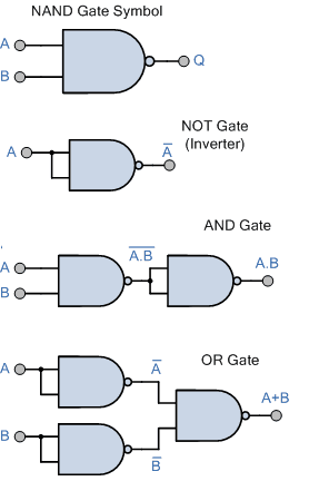
To prove NAND is universal, we show that we can construct NOT, AND, and OR using only NAND gates.

Since we can build NOT, AND, and OR using only NAND gates, we can build any Boolean expression. Therefore, the NAND gate is a Universal Gate.
- ☆3Digital Logic DesignUniversal GateExplain how any Boolean function can be implemented using only universal gates.Combined Bank, O(IT-23), 26 | Officer (IT)
Universal gates are logic gates that can implement any Boolean function without using any other type of gate.
The two universal gates are:
- NAND Gate
- NOR Gate
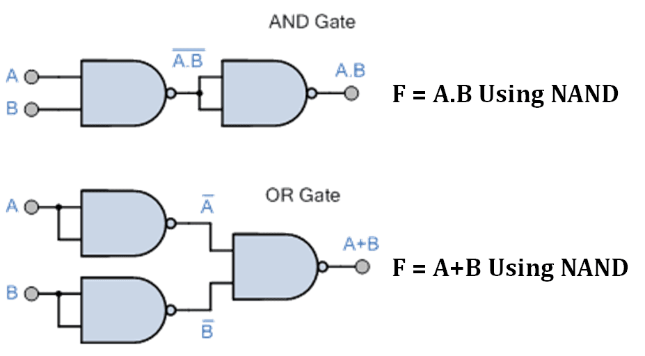
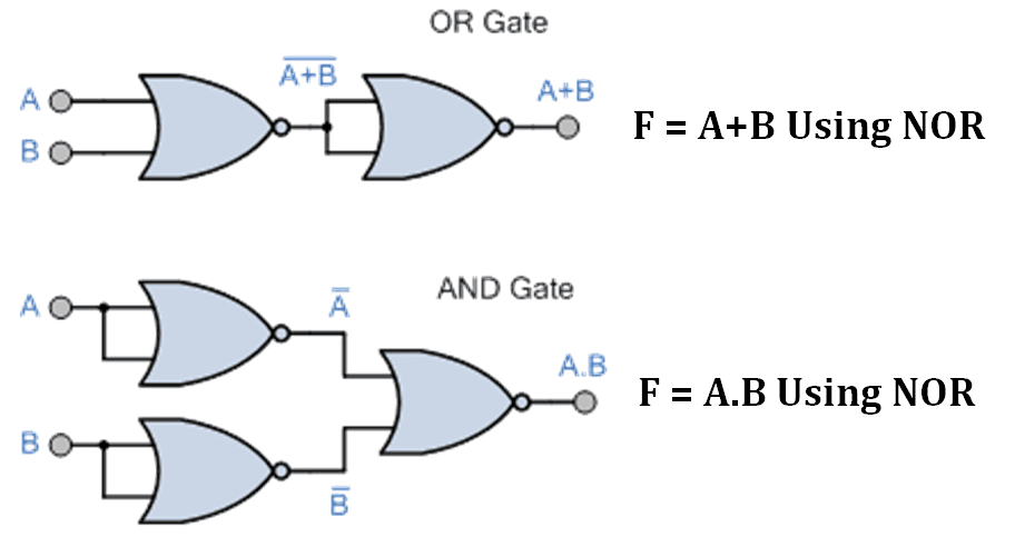
Using only NAND gates or only NOR gates, all basic logic gates such as AND, OR, and NOT can be constructed. Since any Boolean function is built using these basic gates, any Boolean function can also be implemented using universal gates.
Implementation Using NAND Gate
1. NOT Gate using NAND
When both inputs of a NAND gate are connected together:
$$
Y=\overline{A\cdot A}=\overline{A}
$$2. AND Gate using NAND
First NAND operation gives:
(A · B)'Applying another NAND as NOT operation:
$$
Y=\overline{\overline{A\cdot B}}=A\cdot B
$$3. OR Gate using NAND
Using De Morgan’s theorem:
$$
A+B=\overline{\overline{A}\cdot\overline{B}}
$$So OR gate can also be implemented using only NAND gates.
Implementation Using NOR Gate
1. NOT Gate using NOR
When both inputs are same:
$$
Y=\overline{A+A}=\overline{A}
$$2. OR Gate using NOR
First NOR operation gives:
(A + B)'Applying another NOR as NOT operation:
$$
Y=\overline{\overline{A+B}}=A+B
$$3. AND Gate using NOR
Using De Morgan’s theorem:
$$
A\cdot B=\overline{\overline{A}+\overline{B}}
$$Since NAND and NOR gates can create all basic logic gates, and all Boolean functions are formed using basic gates, any Boolean function can be implemented using only NAND gates or only NOR gates.


- ☆4Digital Logic DesignMultiplexer/DemultiplexerWhat is the difference between a Multiplexer and a Demultiplexer? Explain one practical application of each in digital systems.CB, O(IT-24), 26 | Officer (IT)
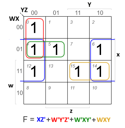
- ☆5Digital Logic DesignKmapSolve the following function using K-map. F (w, x, y, z)= ∑(0,4,5,6,12,14,15)CB, SO(IT), 22 | Senior Officer (IT)

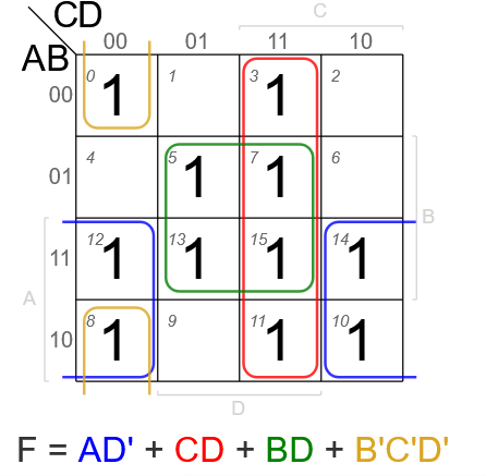
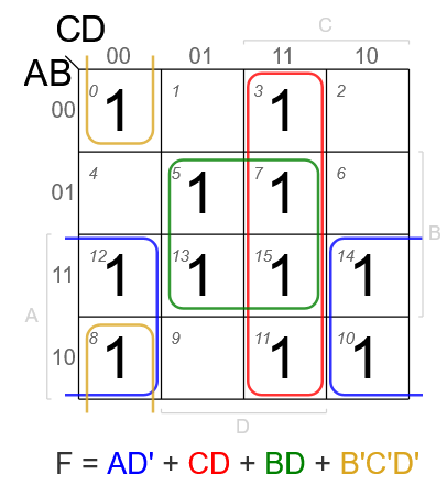
- ☆6Digital Logic DesignKmapSimplify the following boolean expression using 4 variable K-map F (A, B, C, D) = ∑ m(0,3,5,7,8,10,11,12,13,14,15). Draw the K-map grid, clearly show your groupings (loops), and write the final simplified Sum-of-Products (SOP) expressionCombined Bank, SO(IT-24), 26 | Senior Officer (IT)

- ☆7Digital Logic DesignKmapMake a boolean expression using Karnaugh map: ∑m = (3,5,7,9,11,13,14,15)CB, AE(IT)/AHME/SO, 21 | AME/ANE/AE

- ☆8Digital Logic DesignKmapSimplify the following Boolean function using k-map and draw the logic circuit. F = A'B'C' + AB'C' + AB'C + A'BC + ABCJB, ANE, 20 | Assistant Network Engineer
- ☆9Digital Logic DesignBasicDetermine whether the logical statement (P -> Q) -> (P' -> Q') is a tautology, contradiction, or contingency.ICB, AP, 26 | Assistant Programmer
- ☆10Digital Logic DesignBasicDescribe the important characteristics of digital IC's.CB, AME/AHE, 23 | AME/ANE/AE
- ☆11Digital Logic DesignBasicConstruct a Truth Table for a system that triggers an Alarm (Output 1) if: (Motion is Detected AND it is Night Time) OR (Panic Button is Pressed).Combined Bank, O(IT-22), 26 | Officer (IT)
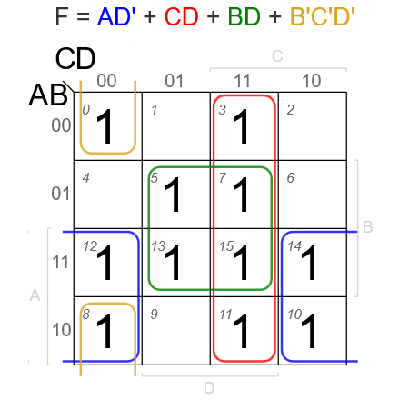
- ☆12Digital Logic DesignkmapSimplify the following boolean expression using 4 variable K-map F(A, B,C,D)=m(0,3,5,7,8,10,11,12,13,14,15).Combined Bank, AE(IT)/AME, 26 | AME/ANE/AE

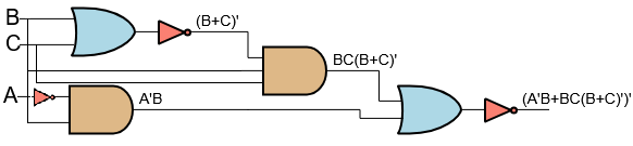
- ☆13Digital Logic DesignBasic GateDraw the logic circuit for the Boolean expression Q = (A'B + BC(B + C)')'. Find the value of Q when (A, B, C) = (1, 0, 1).CB, AE(IT)/AME, 24 | AME/ANE/AE
 (A'B+BC(B+C)')'
∘ Substitute the values A = 1, B = 0, C = 1 into the equation.
= (1'·0+0·1(0+1)')'
= (0·0+0·1(0+1)')'
= (0·0+0·1·1')'
= (0·0+0·1·0)'
= (0+0·1·0)'
= (0+0)'
= 0'
= 1
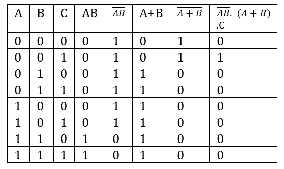
- ☆14Digital Logic DesignBasic GateGiven a logical function, find out the truth table of AB· (A+B).CBB, AD(ICT), 25 | Bangladesh Bank

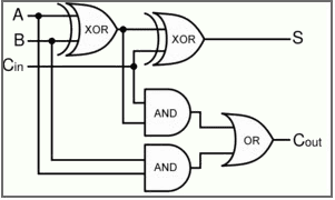
- ☆15Digital Logic DesignBasic GatesDraw the truth table from the follwoing circuit (2 bit input A,B full adder with carry bit Cin)
 Sonali Bank, ADA, 24 | ADA
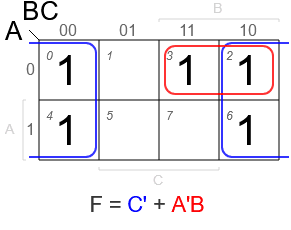
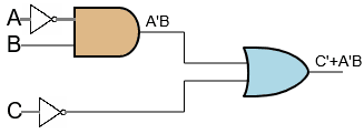
- ☆16Digital Logic DesignBasic GatesSimplify the Boolean algebra: Q = C' + A'B + BC'(B' + C) and draw a logic circuit.Sonali Bank, ADA, 24 | ADA

Logic Circuit:

- ☆17Digital Logic DesignNumber SystemThere are different number systems.
(i) Convert (10010.101)2=(?)10 (ii) Convert (543)10 =(?)16CB, O(IT), 20 | Officer (IT)
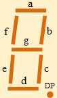
- ☆18Digital Logic DesignFor 7 segments display the input is abcdefg. When a decimal digit or value is display then its equivalent segment is high.
(i) Find out the logical expression in Sum of product for 2bit binary input.Rupali, ANE, 21 |
i) For 2 bit binary, we can find 00, 01, 10, 11 and the equivalent decimal value is 0,1,2,3.
Now, For Binary= 00 (Decimal= 0)= abcdef is high
For Binary= 01 (Decimal=1)= bc is high
For Binary= 10 (Decimal=2) = abged is high For
Binary=11 (Decimal=3)= abgcd is high
- ☆19Digital Logic DesignSimplify the Boolean equation using K-map: F(A,B,C,D) = Σ(0,3,5,7,8,10,11,12,13,14,15).CB, AME/AE(IT-23), 26 | AME/ANE/AE

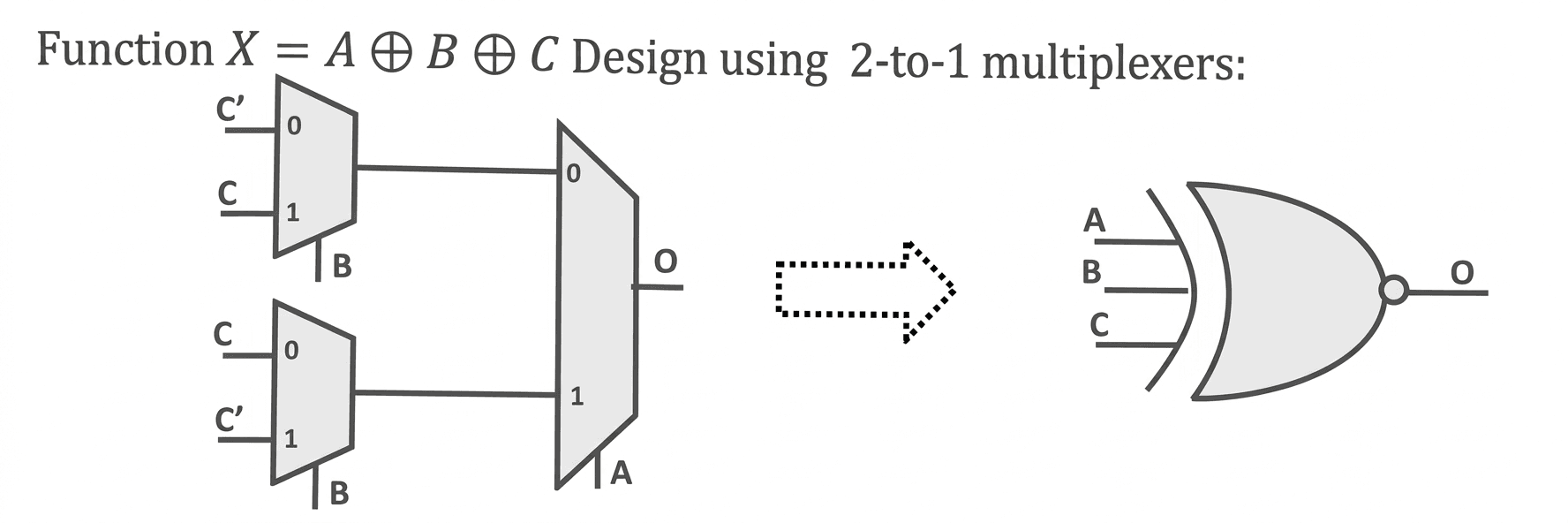
- ☆20Digital Logic DesignDesign a three-input XOR gate with the output function X=A⊕B⊕C using 2-input multiplexers.Dwasa,AME,25 | Other

3-input XOR gate using 2:1 muxes: A 3-input XOR gate returns "1" when the odd number of inputs are "1". The truth table for 3-input XOR gate is shown in figure below.
A B C O 0 0 0 0 0 0 1 1 0 1 0 1 0 1 1 0 1 0 0 1 1 0 1 0 1 1 0 0 1 1 1 1 Truth table for 3-input XOR gate Let us choose A to be the select of mux closest to output. When A is "0", output is a function of B and C. So, we need another mux, let us choose B to be the select of this mux. Among the rows with A = 0, when B is "0", output is equal to C and when B is "1", output is equal to C'.
Similarly among the rows with A = "1", when B is "0", output is equal to C' and when B is "1", output is equal to C. The implementation of 3-input XOR gate using 2:1 muxes is shown in figure below.
- ☆21Digital Logic DesignDraw 16*8 RAM using 16*4 RAM.CB 3 Bank, SO(IT), 20 | Senior Officer (IT)
- ☆22Digital Logic DesignDraw and write the output equation for 8 × 1 multiplexer:
E S2 S1 S0 Output L L L L 0 H H H H D7 H H H L D6 H H L H D5 H H L L D4 H L H H D3 H L H L D2 H L L H D1 H L L L D0 CB 3 Bank, SO(IT), 20 | Senior Officer (IT) - ☆23Digital Logic Design7 segment display, a segment consists of BCD code that represent by ABCD, a segment is on by 2,3,5,6,7,8,9. Write the Boolean expression in SOP form and simplify with Kmap.CB 3 Bank, SO(IT), 20 | Senior Officer (IT)
- ☆24Digital Logic Design
(12345)10 = (?)8
So, (12345)10 = (30071)8
BB, AP, 19 | Assistant Programmer
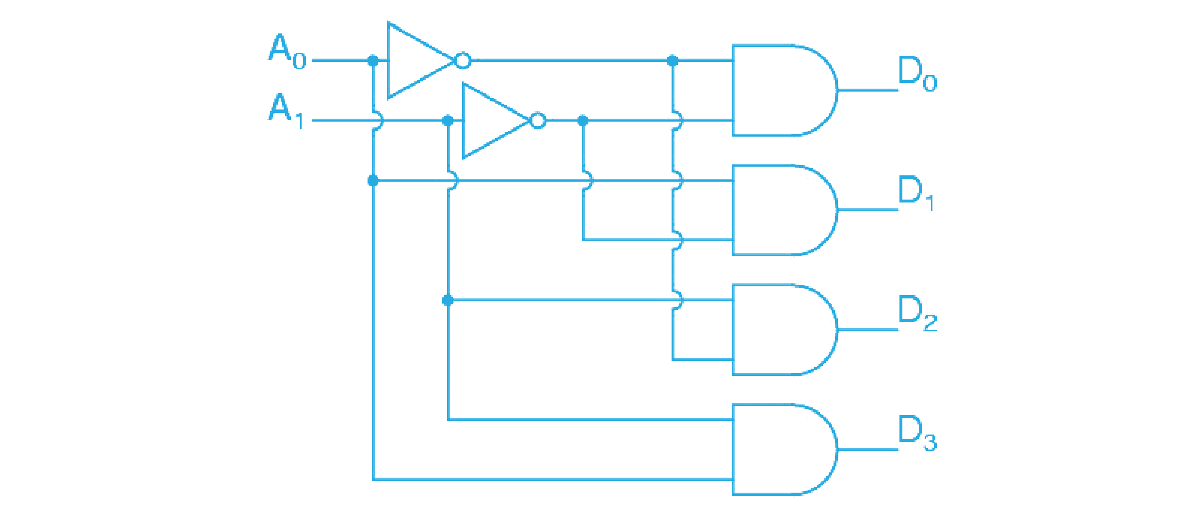
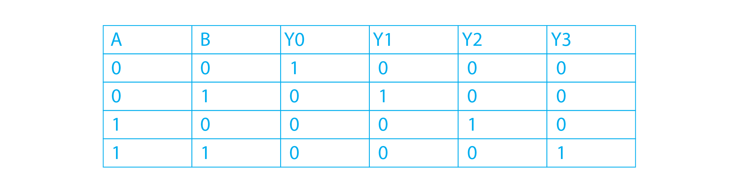
- ☆25Digital Logic DesignDecoder(ii) Draw logic circuit for 2to4 Line decoder/Demulltiplexer.Rupali, ANE, 21 |
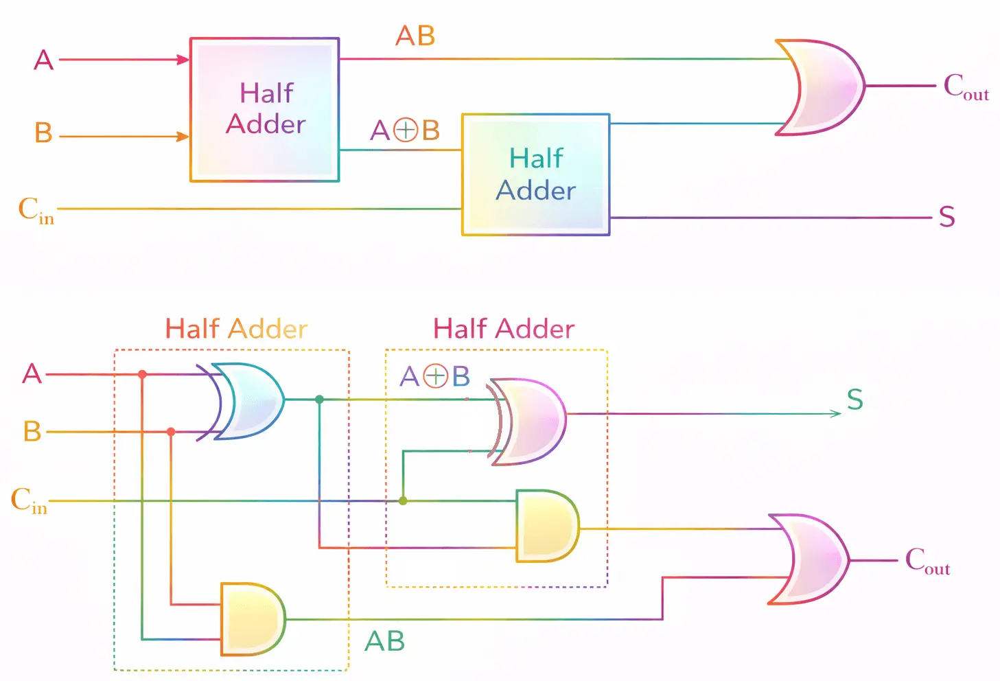
- ☆26Digital Logic DesignAdder CircuitDraw a Full Adder circuit using two half adders.CB, SO(IT), 20 | Senior Officer (IT)


 (A'B+BC(B+C)')'