- 1Error Detection Error DetectionError Detection in Data Link LayerData Link LayerError Detection is the process of identifying whether the data received by a receiver has been corrupted during transmission. In a computer network, data may be changed or corrupted while traveling through a communication medium. Therefore, reliable communication requires mechanisms to detect and, when necessary, correct these errors.
Transmission Error: When data is transmitted from one network node to another, the data may be corrupted because of noise, interference, signal problems, or other transmission issues. The errors caused during data transmission are called Transmission Errors.
Error Control in OSI Model: Error control is mainly associated with the Data Link Layer and Transport Layer of the OSI model. These layers provide mechanisms for detecting and/or handling errors to support reliable data communication.
Types of Transmission Errors
There are mainly two types of transmission errors:- Bit Error
- Burst Error
Example:
Sender sends: 00000010
Receiver receives: 00001010
Here, only one bit has changed from 0 to 1. Therefore, this is a Bit Error.
2. Burst Error: A burst error occurs when two or more bits within a data unit are affected or corrupted during transmission.
The important point is that the burst length is measured from the first corrupted bit to the last corrupted bit, including all bits between them, whether every bit in between is actually corrupted or not.
For example, if the first corrupted bit occurs at position 3 and the last corrupted bit occurs at position 10, the burst length is 8 bits.
Error Detection: Error detection is the process by which the receiver determines whether the received data contains an error. The receiver normally does not have a copy of the original message, so additional information must be transmitted along with the original data.
To make error detection possible, the sender adds some extra bits to the original data. These extra bits are called Redundant Bits or Redundancy.
Basic Error Detection Process:
Original Data → Generator → Redundant Bits → Data + Redundancy → Transmission → Receiver → Checker → Accept / Reject
At the sender side, a generating function or algorithm calculates the redundant information from the original message. The redundant bits are then appended to the original data and transmitted to the receiver.
At the receiver side, a checking function or algorithm examines the received data and calculates or verifies the redundancy. The result is compared with the expected value.
If the check indicates that the data is correct, the receiver accepts the data. If an error is detected, the receiver rejects or discards the data and may request retransmission depending on the protocol.
Redundancy: Redundancy means adding extra information to the original data so that the receiver can detect or correct transmission errors.
For example, if the sender has a message, it passes the message through a generating algorithm. The algorithm produces redundant bits. These redundant bits are appended to the original message and the complete data is transmitted through the communication medium.
The receiver separates or processes the received information using a checking algorithm. If the calculated check matches the expected check, the data is considered valid. Otherwise, an error is detected.
Error Detection vs Error Correction
Error Detection: Error detection determines whether an error has occurred in the received data. It generally results in a simple decision: Accept if the data is valid or Reject if an error is detected.
Error Correction: Error correction attempts to recover the correct data after detecting an error. It is more complex than simple error detection.
There are two common approaches to error correction:- Retransmission: The receiver detects an error and requests the sender to retransmit the entire data unit.
- Error-Correcting Code: Additional redundancy allows the receiver to identify and automatically correct certain types of errors without retransmission.
Error Detection Techniques
There are four commonly discussed error detection techniques in data communication:- Vertical Redundancy Check (VRC)
- Longitudinal Redundancy Check (LRC)
- Checksum
- Cyclic Redundancy Check (CRC)
2. Longitudinal Redundancy Check (LRC): LRC organizes data into rows and columns and adds redundancy based on the bits in each column. It can detect certain errors that may not be detected by a simple parity check.
3. Checksum: In the checksum technique, the sender divides the data into fixed-size units and performs arithmetic operations on those units to generate a checksum value. The checksum is transmitted along with the data. The receiver performs a similar calculation and compares the result to determine whether an error has occurred.
4. Cyclic Redundancy Check (CRC): CRC is a powerful error detection technique based on binary polynomial division. The sender performs a calculation using a predefined generator polynomial and appends the resulting remainder to the data. The receiver performs a similar calculation to determine whether the received data has been corrupted.
CRC and Checksum are widely used error detection mechanisms in computer networks and communication protocols. CRC is particularly effective at detecting burst errors.
- 2Error Detection ParityExplain Parity Bit. How error is detected by Parity Biit?Data Link LayerParity Bit: A parity bit is an additional bit added to a data sequence to detect errors during data transmission. It is the simplest type of error-detecting code.
There are two types of parity: Even Parity and Odd Parity.
Even Parity: The parity bit is selected so that the total number of 1s in the transmitted code, including the parity bit, becomes even.
Example:
Data = 10101
Number of 1s = 3 (odd)
Therefore, parity bit = 1
Transmitted code = 101011
Total number of 1s = 4 (even)
Odd Parity: The parity bit is selected so that the total number of 1s in the transmitted code, including the parity bit, becomes odd.
Example:
Data = 10101
Number of 1s = 3 (odd)
Therefore, parity bit = 0
Transmitted code = 101010
Total number of 1s = 3 (odd)
Error Detection: At the receiver side, a parity checker checks the number of 1s in the received code. If the required parity is not maintained, an error is detected.
Example: Suppose even parity is used and the transmitted code is 101011. If one bit changes during transmission and the receiver gets 101001, the number of 1s becomes 3, which is odd. Therefore, the receiver detects an error.
Important Points:
• Parity can detect odd numbers of bit errors.
• Parity cannot detect an even number of bit errors.
• A parity bit can detect an error, but it cannot identify the exact location of the error.
• Therefore, a simple parity bit cannot correct the error.
Parity Bit: ডেটা ট্রান্সমিশনের সময় error শনাক্ত করার জন্য মূল ডেটার সাথে একটি অতিরিক্ত bit যোগ করা হয়, যাকে Parity Bit বলে। এটি একটি সহজ ধরনের error-detecting code.
Parity দুই ধরনের: Even Parity এবং Odd Parity।
Even Parity: Parity bit এমনভাবে নির্ধারণ করা হয় যাতে parity bit-সহ সম্পূর্ণ code-এ মোট 1-এর সংখ্যা জোড় হয়।
উদাহরণ:
Data = 10101
1-এর সংখ্যা = 3 (বিজোড়)
তাই parity bit = 1
Transmitted code = 101011
মোট 1-এর সংখ্যা = 4 (জোড়)
Odd Parity: Parity bit এমনভাবে নির্ধারণ করা হয় যাতে parity bit-সহ সম্পূর্ণ code-এ মোট 1-এর সংখ্যা বিজোড় হয়।
উদাহরণ:
Data = 10101
1-এর সংখ্যা = 3 (বিজোড়)
তাই parity bit = 0
Transmitted code = 101010
মোট 1-এর সংখ্যা = 3 (বিজোড়)
Error Detection: Receiver-এর parity checker প্রাপ্ত code-এ 1-এর সংখ্যা গণনা করে। নির্ধারিত parity বজায় না থাকলে receiver error শনাক্ত করতে পারে।
উদাহরণ: ধরা যাক, Even Parity ব্যবহার করা হয়েছে এবং transmitted code হলো 101011। Transmission-এর সময় একটি bit পরিবর্তিত হয়ে receiver 101001 পেল। এখানে 1-এর সংখ্যা 3, অর্থাৎ বিজোড়। তাই receiver বুঝতে পারে যে একটি error হয়েছে।
গুরুত্বপূর্ণ বিষয়:
• Parity দ্বারা বিজোড় সংখ্যক bit error শনাক্ত করা যায়।
• জোড় সংখ্যক bit error শনাক্ত করা যায় না।
• Parity bit error শনাক্ত করতে পারে, কিন্তু error-এর সঠিক অবস্থান নির্ণয় করতে পারে না।
• তাই simple parity bit দিয়ে error correct করা যায় না।
- 3Error Detection ChecksumError Detection Technique : ChecksumData Link LayerWhat is Checksum?
Checksum is an Error Detection Technique used in computer networks to detect whether data has been corrupted during transmission. At the sender side, the original data is divided into fixed-size blocks, the blocks are added together, and the One's Complement of the final sum is calculated as the checksum. The checksum is then appended to the original data and transmitted to the receiver.
How Checksum Works:- Divide the Data: Divide the original message into equal-sized blocks of n bits.
- Add the Blocks: Add all the blocks using binary addition.
- Wrap the Carry: If an extra carry is produced, add that carry back to the least significant bit of the result. This is called End-Around Carry.
- Find One's Complement: Invert every bit of the final sum. 0 becomes 1 and 1 becomes 0.
- Generate Checksum: The resulting value is the checksum.
- Append and Transmit: Append the checksum to the original data and send the complete information to the receiver.
- Receiver Verification: The receiver adds all received data blocks, including the checksum, using the same carry wrap-around method.
- Accept or Reject: If the final result contains all 1s, the data is considered error-free and accepted. Otherwise, an error is detected and the data is rejected.
- 4Error Detection ChecksumExample & Performance of ChecksumData Link LayerExample: Suppose the original data is:
10011001111000100010010010000100
Assume the data is divided into four 8-bit blocks:
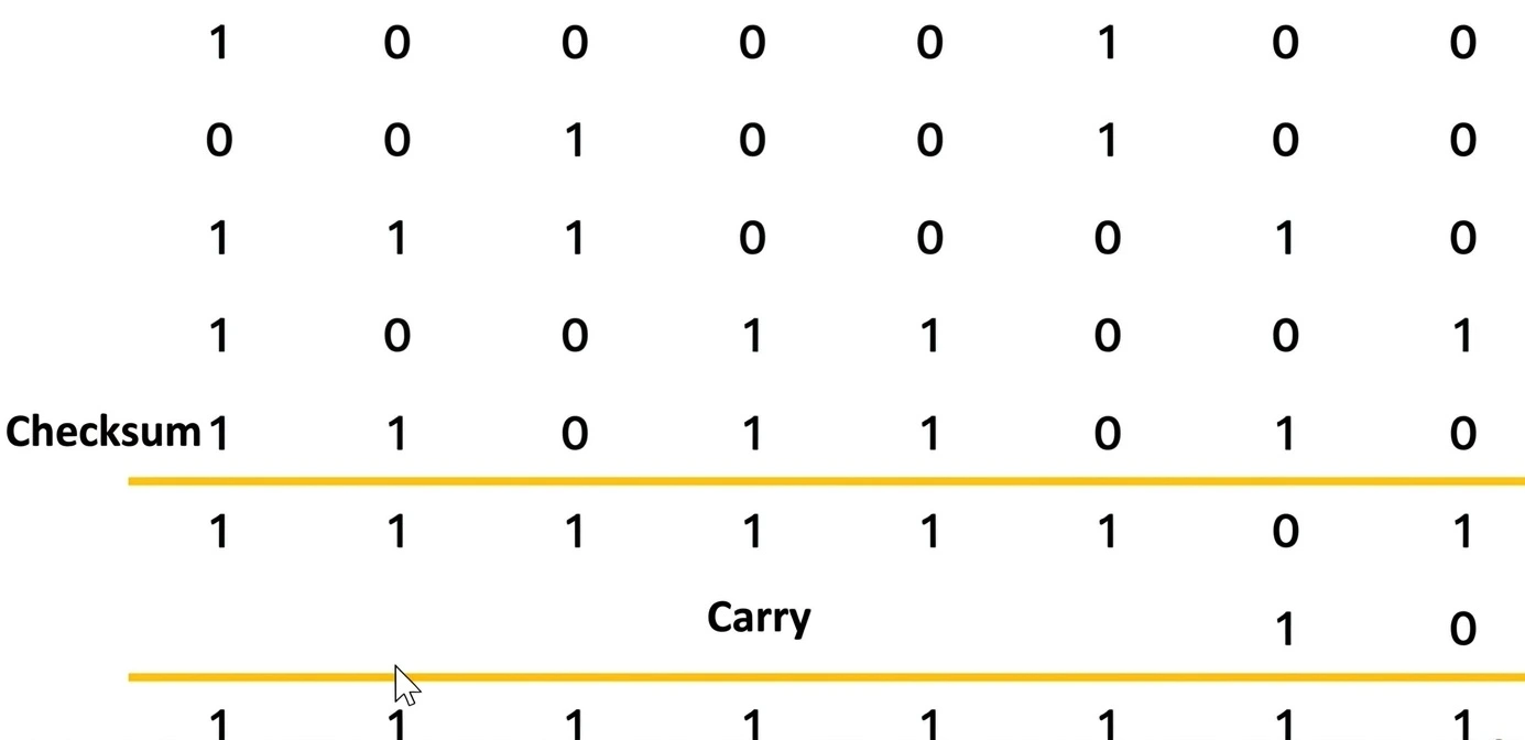
Step 1 — Add the Blocks:10011001 11100010 00100100 10000100 10011001 11100010 00100100 10000100 ----------------- 00100011 + 10 --------------- 00100101
The resulting 8-bit sum is: 00100101
Step 2 — One's Complement(invert): 00100101→ 11011010 (It is Checksum)
Step 3 — Transmitted Data:
The sender appends the checksum to the original data: 1101101010011001111000100010010010000100
Step 4 — Receiver Verification:
The receiver adds all four data blocks and the received checksum. If the final result is: 11111111
then the receiver assumes that no transmission error has been detected and accepts the data. otherwise rejected.

Performance of Checksum- Simple and easy to implement.
- Requires relatively little computational overhead.
- Can detect many single-bit, multiple-bit, and burst errors.
- Widely used in network and communication protocols.
- 5Error Detection CRCCRC and Step of CRCData Link LayerCRC (Cyclic Redundancy Check) is an error-detection technique used in the Data Link Layer to detect whether data has been corrupted during transmission.
Steps of CRC Process
Choose a Generator Polynomial — Sender and receiver agree on a binary divisor called the Generator.
Append Zeros — Add n-1 zeros to the original data, where n is the number of bits in the generator.
Binary Division — Divide the resulting bit sequence by the generator using XOR division.
Find Remainder — The remainder obtained from the division is called the CRC.
Create Codeword — Append the CRC remainder to the original data.
Transmit — Send the resulting data + CRC to the receiver.
Receiver Checks — Receiver divides the received codeword by the same generator.
Check Remainder:
Remainder = 0 → No error detected.
Remainder ≠ 0 → Error detected.
Shortcut:
Data → Append Zeros → XOR Division → CRC Remainder → Append CRC → Transmit → Divide → Check Remainder
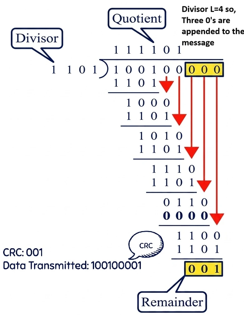
- 6Error Detection CRCFind the CRC for the data blocks 100100 with the divisor 1101?Data Link Layer
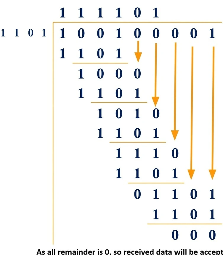
- 7Error Detection CRCReceiver received data 100100001 and the divisor is 1101 , Check the received Data will be accepted or not.Data Link Layer
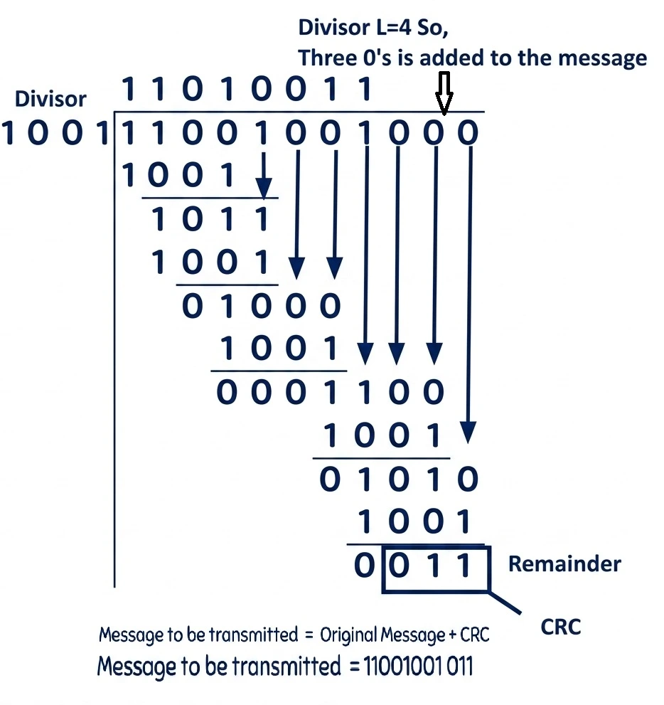
- 8Error Detection CRCThe message 11001001 is to be transmitted using CRC polynomial x3+1 to protect it from errors. Find the message that should be transmitted.Data Link Layer
Error Detection and Correction Code Example ( Hamming Code)
Given Data (m): 1011 → Length of data, $m = 4$
Formula: 2r ≥ m + r + 1
For r = 2: 22 ≥ 4 + 2 + 1 ⇒ 4 ≥ 7 (False)
For r = 3: 23 ≥ 4 + 3 + 1 ⇒ 8 ≥ 8 (True)
Selected r = 3. Total bits = $m + r = 4 + 3 = 7$ bits.
Place parity bits at positions that are powers of 2 (1, 2, 4):
| 7 | 6 | 5 | 4 | 3 | 2 | 1 |
|---|---|---|---|---|---|---|
| 1 | 0 | 1 | R3 | 1 | R2 | R1 |
Binary Position Table
| Position | R3 (4) | R2 (2) | R1 (1) |
|---|---|---|---|
| 0 | 0 | 0 | 0 |
| 1 (R1) | 0 | 0 | 1 |
| 2 (R2) | 0 | 1 | 0 |
| 3 | 0 | 1 | 1 |
| 4 (R3) | 1 | 0 | 0 |
| 5 | 1 | 0 | 1 |
| 6 | 1 | 1 | 0 |
| 7 | 1 | 1 | 1 |
Parity Bit Values
Bit Coverages:
- R1 covers positions (1, 3, 5, 7)
- R2 covers positions (2, 3, 6, 7)
- R3 covers positions (4, 5, 6, 7)
Even Parity Calculation:
R1 → (R1, Bit3, Bit5, Bit7) → (R1, 1, 1, 1) ⇒ R1 = 1 (to make count of 1s even)
R2 → (R2, Bit3, Bit6, Bit7) → (R2, 1, 0, 1) ⇒ R2 = 0 (already even)
R3 → (R3, Bit5, Bit6, Bit7) → (R3, 1, 0, 1) ⇒ R3 = 0 (already even)
Final Transmitted Hamming Code:
| 7 | 6 | 5 | 4 | 3 | 2 | 1 |
|---|---|---|---|---|---|---|
| 1 | 0 | 1 | 0 | 1 | 0 | 1 |
Transmitted Data: 1010101
Received Data: 1110101
| 7 | 6 | 5 | 4 | 3 | 2 | 1 |
|---|---|---|---|---|---|---|
| 1 | 1 | 1 | 0 | 1 | 0 | 1 |
Even Parity Check:
P1 (Positions 1, 3, 5, 7) → bits (1, 1, 1, 1) → Total 1s = 4 (Even) ⇒ 0
P2 (Positions 2, 3, 6, 7) → bits (0, 1, 1, 1) → Total 1s = 3 (Odd) ⇒ 1
P3 (Positions 4, 5, 6, 7) → bits (0, 1, 1, 1) → Total 1s = 3 (Odd) ⇒ 1
Error Location Calculation:
Syndrome Bits: (P3, P2, P1) = (1, 1, 0)2
Conclusion: Yes, there is an error! The error is located at Bit Position 6.
Correcting bit position 6 from 1 to 0 restores the original data: 1010101.